
Method and magnetic resonance apparatus with reduction of audible noise by shortening the acquisition time for individual interior k-space lines

a technology of audible noise and magnetic resonance, which is applied in the field of method and magnetic resonance system for acquiring mr data, can solve the problems of strong vibration of the entire structure of the magnetic resonance scanner, and achieve the effect of reducing the loudness of the magnetic resonance system

Active Publication Date: 2018-07-03
SIEMENS HEALTHCARE GMBH
View PDF3 Cites 0 Cited by
  • Summary
  • Abstract
  • Description
  • Claims
  • Application Information

AI Technical Summary

Benefits of technology

Significantly reduces the loudness of the magnetic resonance system during data acquisition, with less than 6% of the acquisition time being 'loud', allowing for a quieter measurement process without compromising image quality.

Problems solved by technology

If there is a rapid change in the magnetic field gradients, and hence a rapid change in the Lorentz forces, this results in strong vibrations of the entire structure of the magnetic resonance scanner.

Method used


Image

  • Method and magnetic resonance apparatus with reduction of audible noise by shortening the acquisition time for individual interior k-space lines
  • Method and magnetic resonance apparatus with reduction of audible noise by shortening the acquisition time for individual interior k-space lines
  • Method and magnetic resonance apparatus with reduction of audible noise by shortening the acquisition time for individual interior k-space lines

Examples


Embodiment Construction

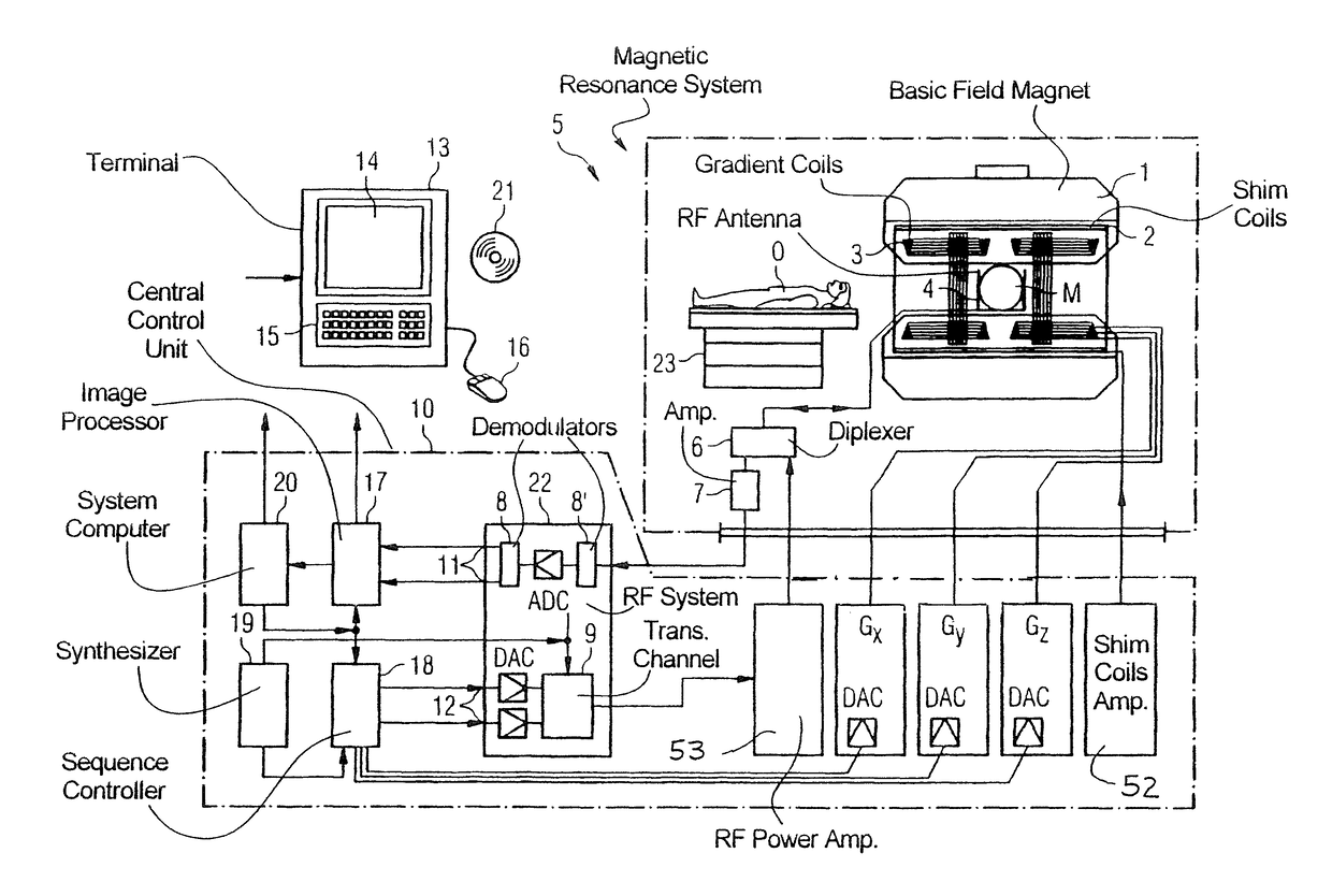
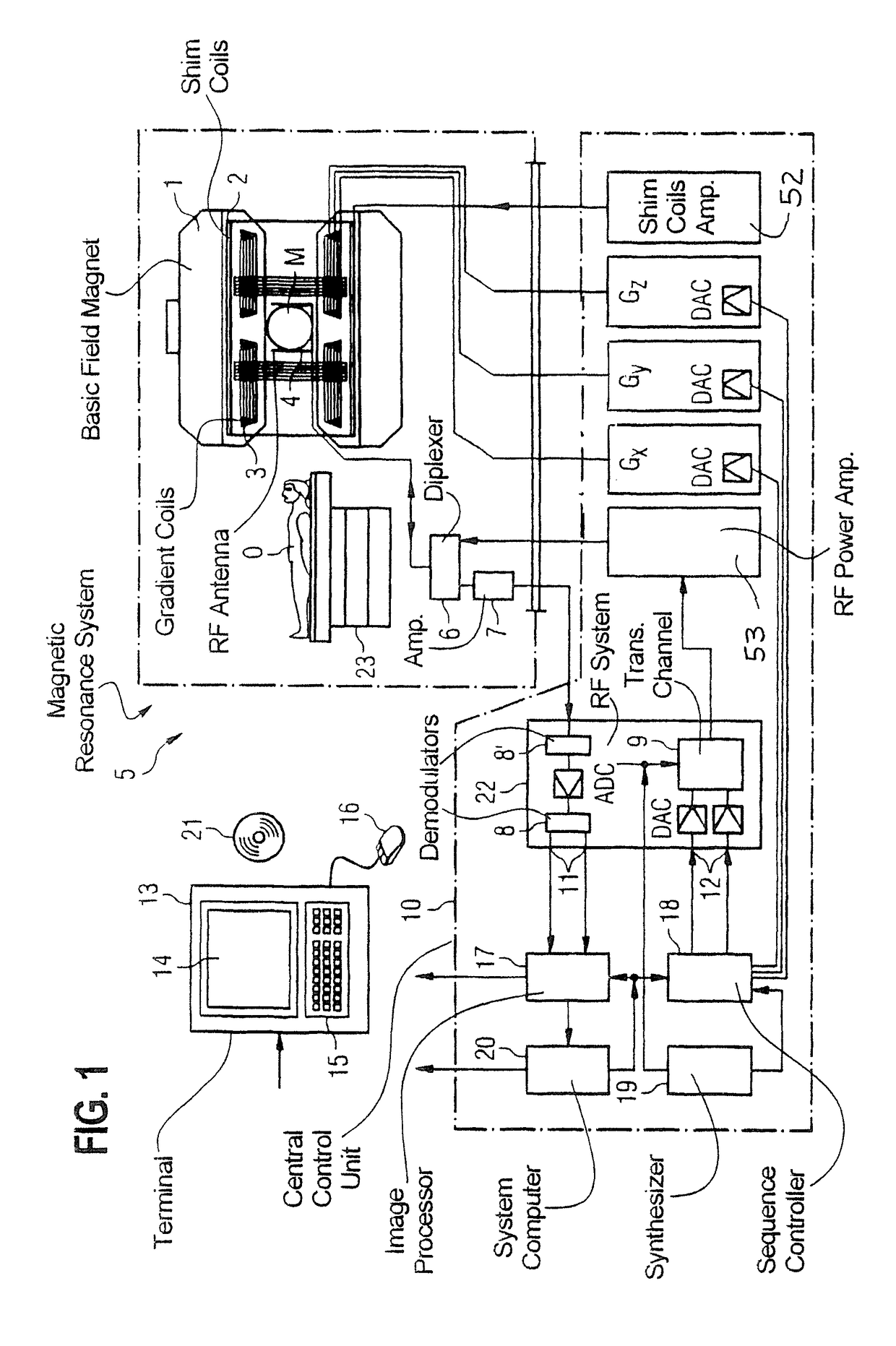
[0065]FIG. 1 schematically illustrates a magnetic resonance scanner 5 (of a magnetic resonance imaging or nuclear spin tomography apparatus). In this case a basic field magnet 1 generates a strong magnetic field that is constant with respect to time in order to polarize or align the nuclear spins in an examination region of an object O, such as e.g. a part of a human body that is to be examined, which is arranged lying on a table 23 in the magnetic resonance system 5. The high degree of homogeneity of the basic magnetic field that is required for the nuclear spin resonance measurement is defined in a typically spherical measurement volume M in which the parts of the human body that are to be examined are arranged. In order to support the homogeneity requirements and in particular to eliminate time-invariable influences, elements called shim plates made of ferromagnetic material are mounted at suitable points. Time-variable influences are eliminated by shim coils 2 that are supplied ...


PUM


Abstract

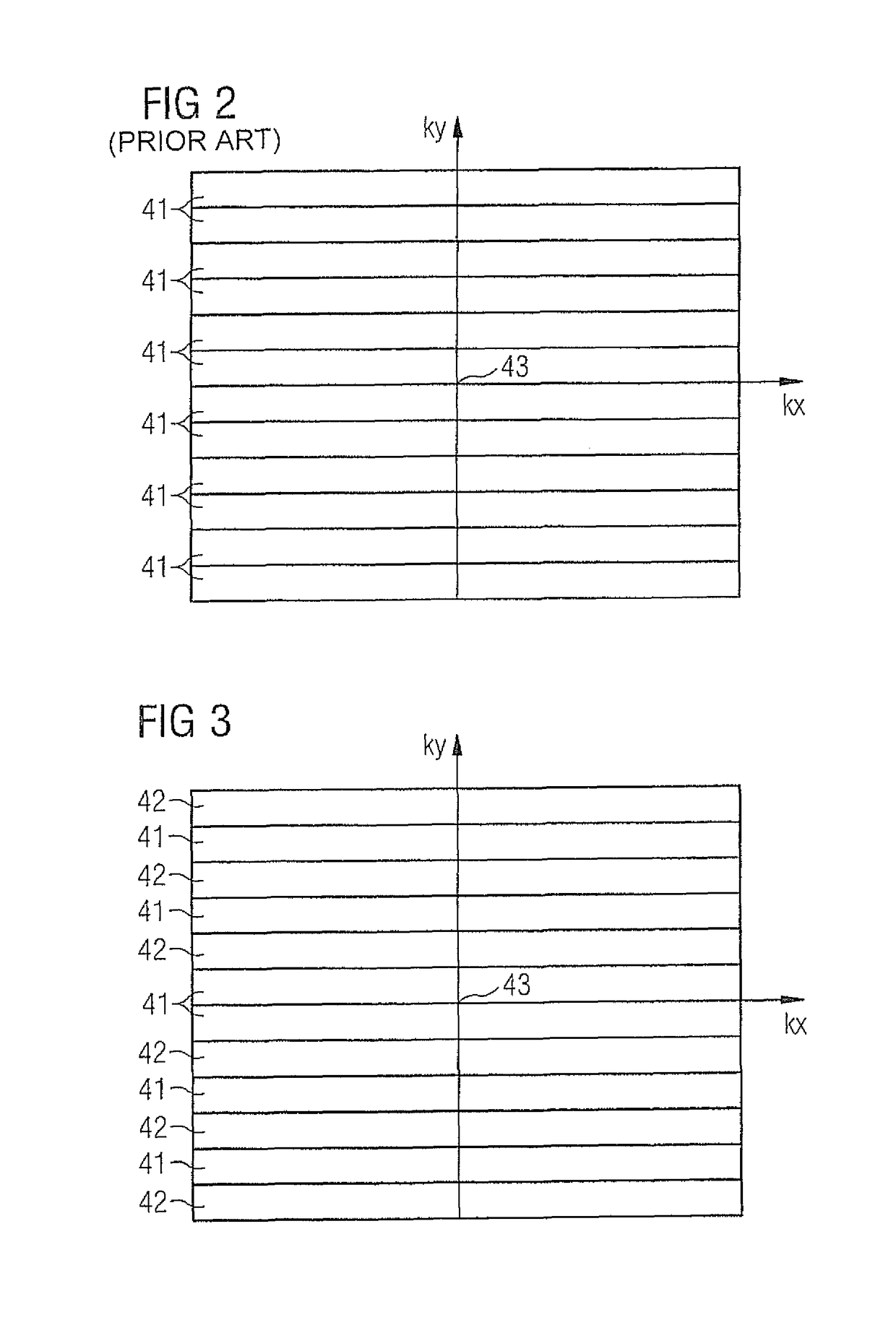
For each k-space line, a time period is defined that starts with the application of the RF pulse directly prior to the acquisition of the respective k-space line, and ends at the time point of the echo during the acquisition of the MR data of the respective k-space line. This time period is set shorter for those k-space lines that lie in a central region of k-space than for k-space lines that lie outside of the central region.

Description

CROSS-REFERENCE TO RELATED APPLICATIONS[0001]Not applicable.BACKGROUND OF THE INVENTION[0002]The present invention relates to a method and a magnetic resonance system for acquiring MR data in a volume segment of an examination subject.DESCRIPTION OF THE PRIOR ART[0003]In order to acquire MR data, magnetic field gradients are switched, among other things. Considerable current intensities occur when the magnetic field gradients are switched. Because the gradient coils by means of which the magnetic field gradients are generated are located within the main magnetic field (B0 field) of the magnetic resonance scanner, this causes a Lorentz force to be generated, which leads to a mechanical excitation of the gradient system of the magnetic resonance system. If there is a rapid change in the magnetic field gradients, and hence a rapid change in the Lorentz forces, this results in strong vibrations of the entire structure of the magnetic resonance scanner. These vibrations can also be trans...

Claims


Application Information

Patent Timeline
Patent Type & Authority Patents(United States)
IPC IPC(8): G01V3/00G01R33/30G01R33/34G01R33/385G01R33/56G01R33/48G01R33/561
CPCG01R33/4822G01R33/30G01R33/3852G01R33/5608G01R33/34092G01R33/5617
Inventor OTT, MARTIN
Owner SIEMENS HEALTHCARE GMBH
Learn More