Fan and fan module

a technology of fan and module, applied in the direction of liquid fuel engine components, pump components, non-positive displacement fluid engines, etc., can solve the problem of more noise in the back sweep fan, and achieve the effect of reducing the noise in the fan, preserving the high performance of the typical back sweep fan, and improving performan

Inactive Publication Date: 2018-07-10
BROSE FAHRZEUGTEILE GMBH & CO KG HALLSTADT (DE)
View PDF4 Cites 0 Cited by
  • Summary
  • Abstract
  • Description
  • Claims
  • Application Information

AI Technical Summary

Benefits of technology

[0007]Since the maximum ratio r / R of the lower back sweep portion of the fan blade is at least r / R=0.90 and further the fan blade comprises in addition to the lower back sweep portion an upper forward sweep portion it is possible to reduce fan noise and still keep high performance of a typical back sweep fan. Therefore a fan with a better performance, higher efficiency and lower noise level can be provided.

Problems solved by technology

But in general back sweep fan creates more noise than comparable forward sweep fan.

Method used


Image

  • Fan and fan module
  • Fan and fan module
  • Fan and fan module

Examples


Embodiment Construction

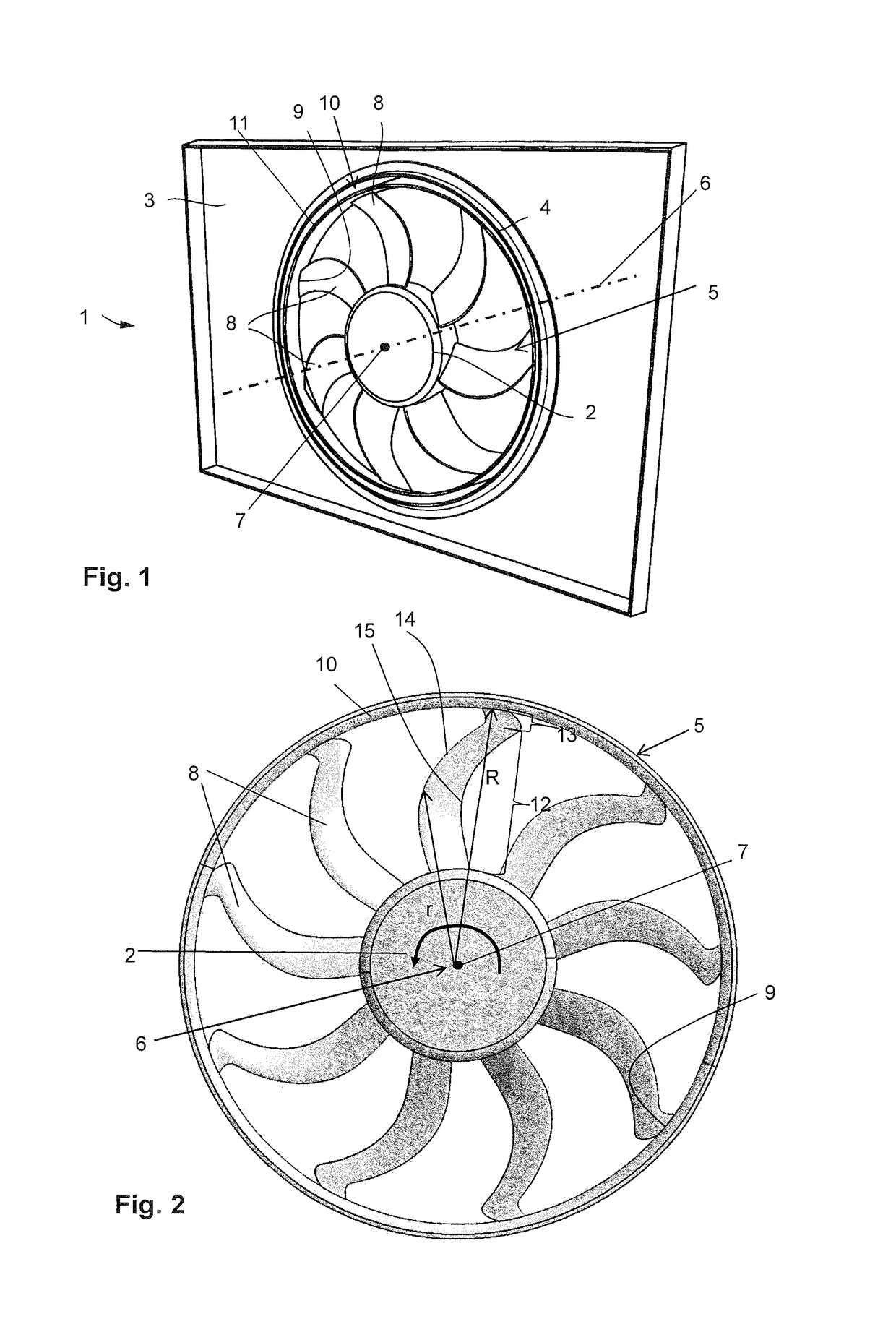
[0025]FIG. 1 shows a perspective front view of an exemplary cooling fan module 1 for a vehicle. The cooling fan module 1 comprises a frame 3 provided with an opening 4 on which a fan 5 is located.

[0026]In FIG. 1 a conventional fan 5 is shown to be replaced by an inventive fan which will be described in the following with respect to FIGS. 2 to 4.

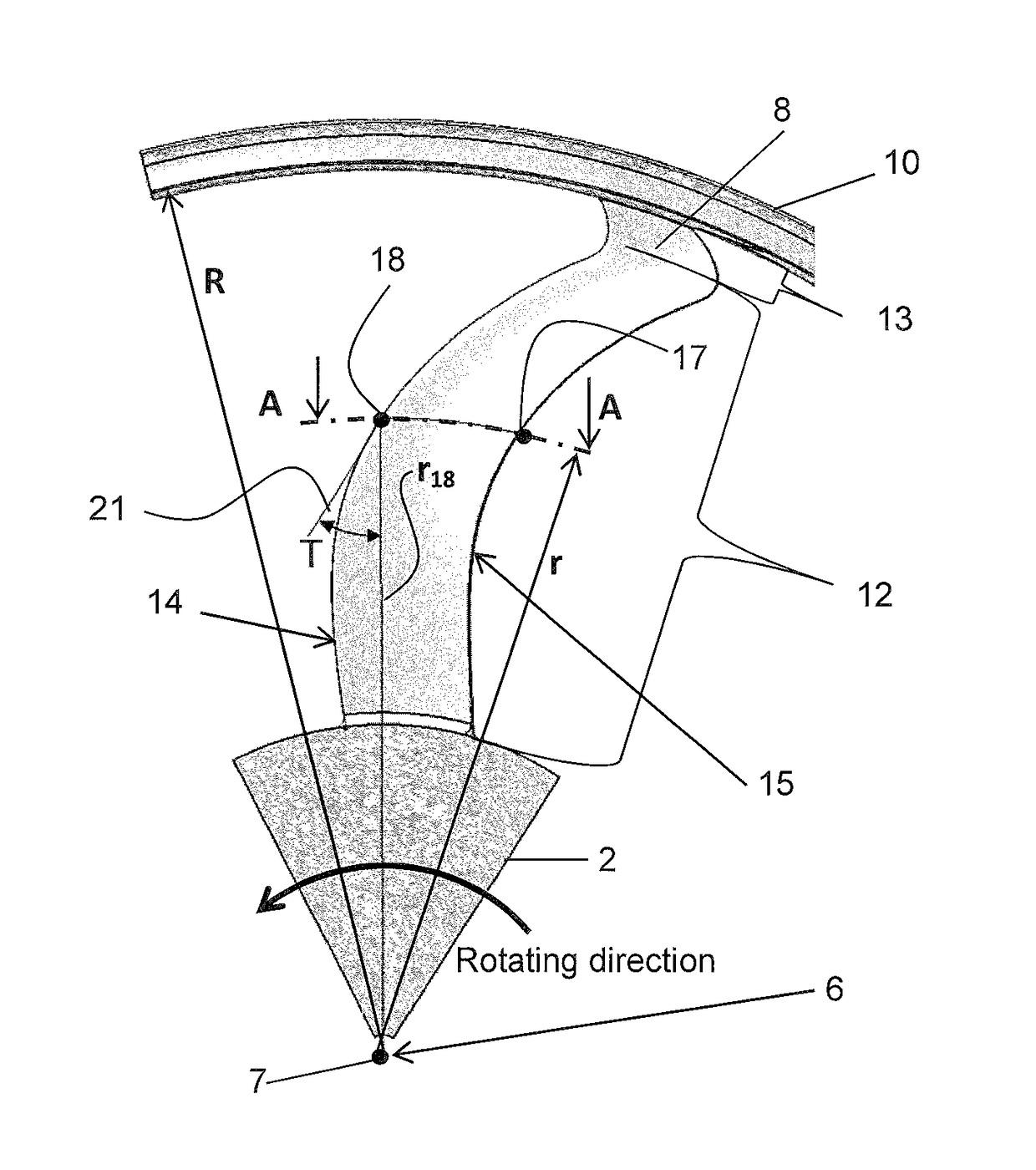
[0027]The fan 5 is fixed to a motor shaft, and the motor (not shown in FIG. 1) is located inside a fan hub 2 and fixed to the frame 3 by assembly means, e.g. struts etc., not shown in FIG. 1. The fan 5 can rotate around a rotation axis 6 by means of the motor shaft rotating inside the motor. The center 7 of the fan 5 and the rotation axis 6 of the fan 5 are indicated in FIG. 1.

[0028]Furthermore, the fan 5, in particular an axial fan, comprises a plurality of fan blades 8. The fan blades 8 in FIG. 1 are crescent-shaped toward the rear.

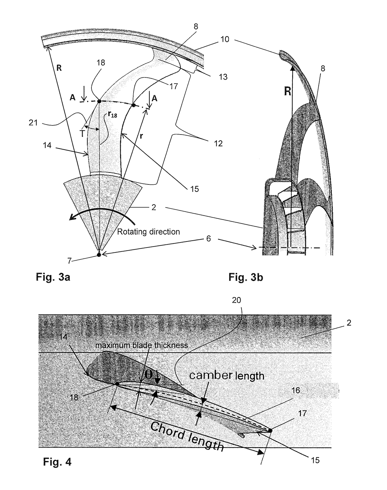
[0029]The fan blades 8 are attached at their lower end to the fan hub 2 and are further connected to one anoth...


PUM


Abstract

The invention relates to a fan and a fan module, wherein the fan comprises: a fan hub which comprises a fan rotation axis to rotate in a predetermined direction, a plurality of fan blades comprising a lower end and an upper end, wherein each fan blade is attached with its lower end to the fan hub and extends radially outwardly from the fan hub, wherein each fan blade comprises a lower back sweep portion and an upper forward sweep portion, wherein a maximum ratio r / R of the lower back sweep portion is at least 0.90, wherein r is the local radius of a point of the fan blade edge, and R is the radius of the upper end of the fan blade.

Description

FIELD OF THE INVENTION[0001]The present invention relates to a fan and a fan module, in particular a cooling fan module in the automotive field, e.g., for a motor vehicle.TECHNICAL BACKGROUND[0002]Fan modules such as cooling fan modules are generally used to cool the engine in motor vehicles. Generally a fan module consists of a fan, a motor located at the centre of the fan to drive the fan, and a frame which comprises assembly struts for fixing the motor. Further, the fan of a cooling fan module is designed to produce an air flow with which the heat generated by the engine is removed.[0003]As a fan of the fan module, in particular cooling fan module, a forward sweep fan or a back sweep fan are commonly used. Comparing with a forward sweep fan, a back sweep fan of a cooling fan module of a vehicle has good efficiency over a wider operating range and higher pressure rise at high flow rate, which is needed, when vehicle is under trailer towing condition at 50 to 60 mile per hour speed...

Claims


Application Information

Patent Timeline
Patent Type & Authority Patents(United States)
IPC IPC(8): F04D29/38
CPCF04D29/384
Inventor HONG, TAOMUDGE, DEREK
Owner BROSE FAHRZEUGTEILE GMBH & CO KG HALLSTADT (DE)
Why Eureka
Try Eureka