Combustion type water heater

a water heater and combustion technology, applied in indirect heat exchangers, heating types, lighting and heating apparatuses, etc., can solve the problems of increasing product size and manufacturing costs, increasing exhaust gas temperature, and increasing exhaust gas temperatur

a water heater and combustion technology, applied in indirect heat exchangers, heating types, lighting and heating apparatuses, etc., can solve the problems of increasing product size and manufacturing costs, increasing exhaust gas temperature, and increasing exhaust gas temperatur

US10018376B2Active Publication Date: 2018-07-10RINNAI CORP

Image

  • Combustion type water heater
  • Combustion type water heater
  • Combustion type water heater

Examples


Embodiment Construction

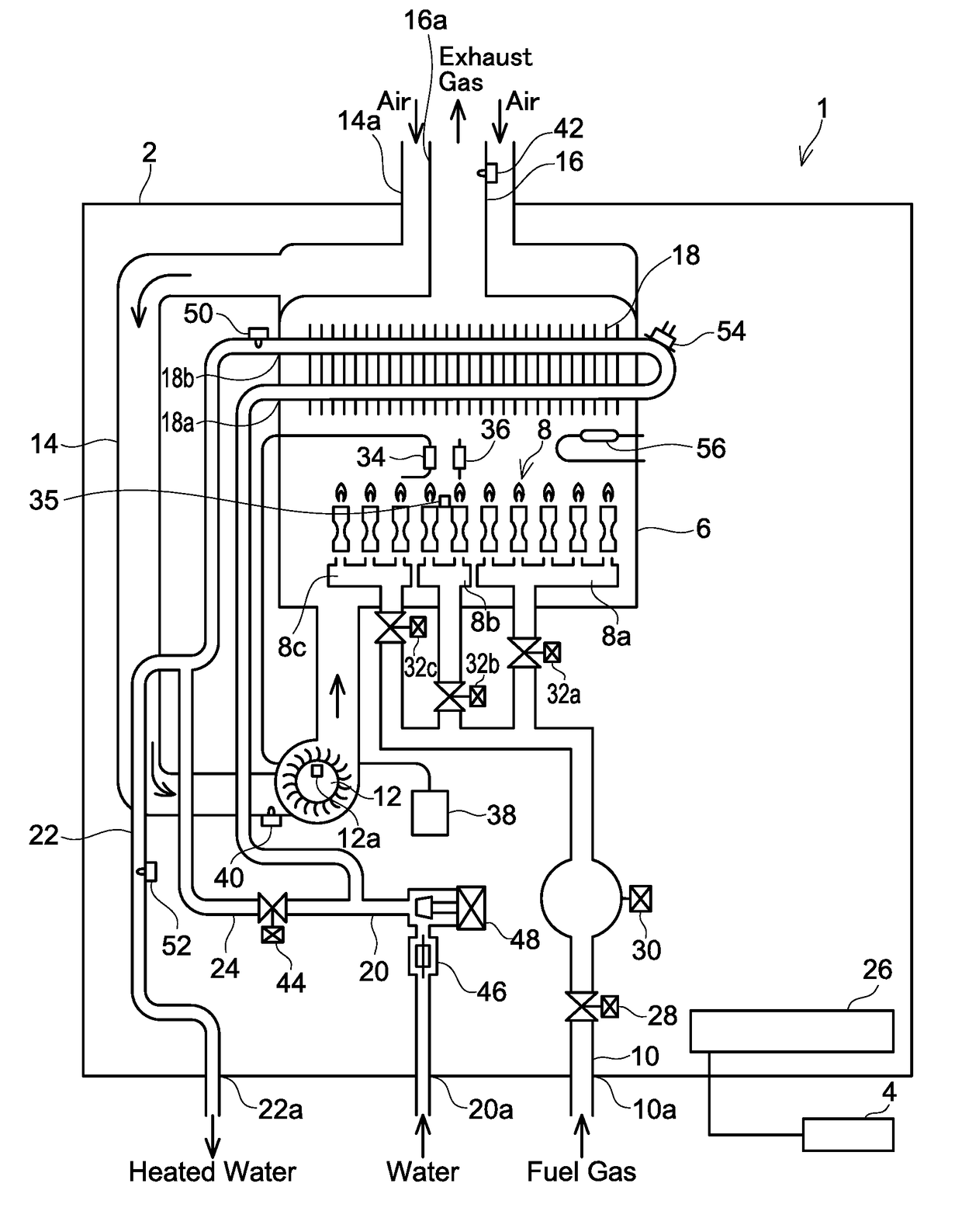
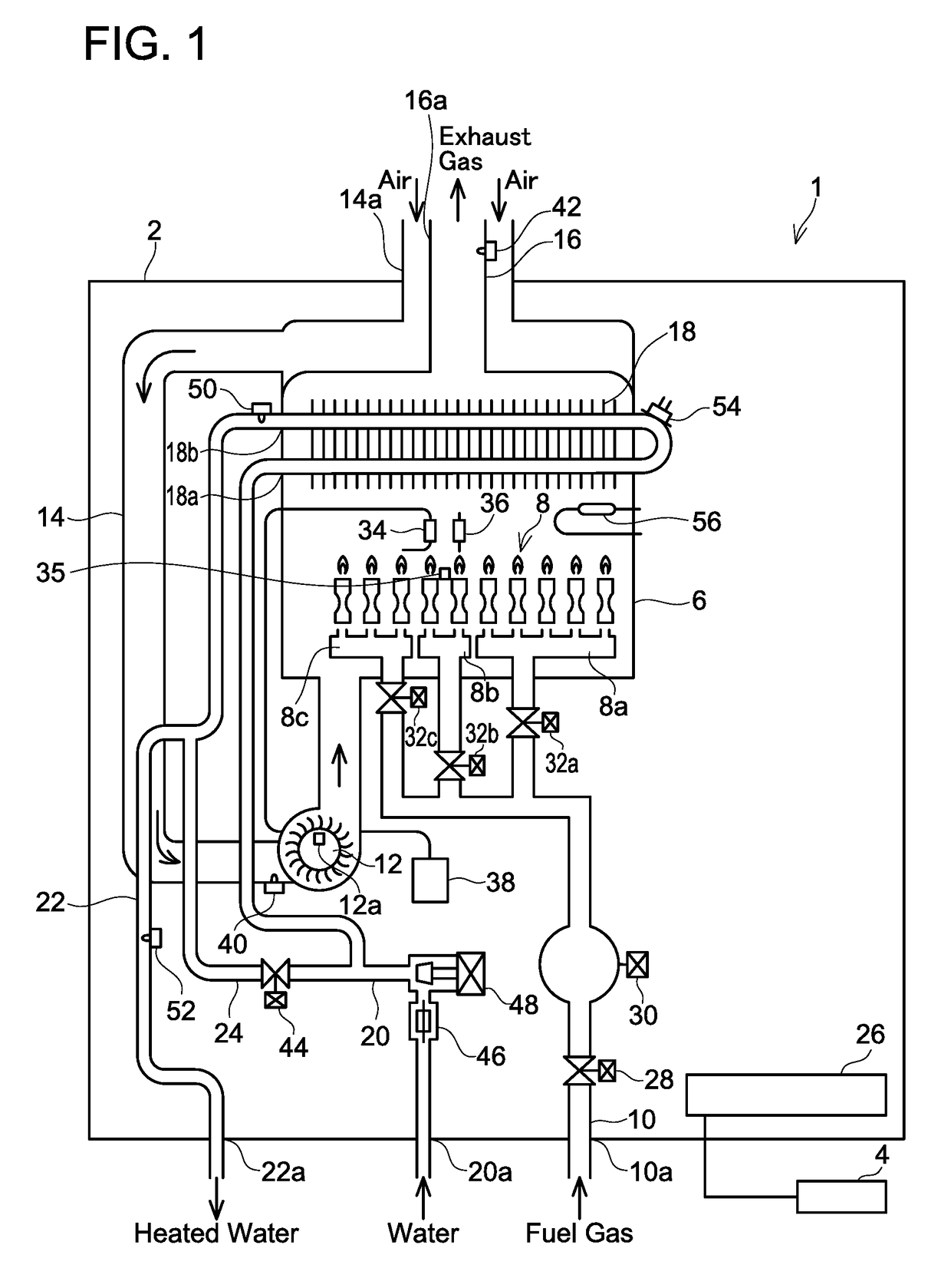
[0021]As shown in FIG. 1, a water heater 1 of an embodiment of a combustion type water heater comprises a water heater body 2, and a remote controller 4 for remotely controlling the water heater body 2. The water heater body 2 primarily includes a combustion chamber 6, a burner 8, a fuel gas supply pipe 10, a fan 12, an air supply pipe 14, an exhaust pipe 16, a heat exchanger 18, a water input pipe 20, a heated water output pipe 22, a bypass pipe 24, and a controller 26.

[0022]The burner 8 and the heat exchanger 18 are arranged inside the combustion chamber 6. The heat exchanger 18 is arranged above the burner 8. The burner 8 of the present embodiment is an all-primary air burner. In another embodiment, the burner 8 may be a Bunsen burner. The burner 8 is composed of three combustion sections with different combustion amounts (namely a first combustion section 8a, a second combustion section 8b, and a third combustion section 8c), and plural levels of combustion amount ranges can be ...


PUM


Abstract

The present description discloses a combustion type water heater that heats water by burning fuel. The combustion type water heater includes: a burner that generates combustion gas by burning the fuel; a heat exchanger that exchanges heat between the water passing through on an inside of the heat exchanger and the combustion gas flowing on an outside of the heat exchanger, an exhaust pipe that discharges the combustion gas after the heat exchange in the heat exchanger as exhaust gas; an exhaust gas temperature detector that detects a temperature of the exhaust gas flowing in the exhaust pipe as an exhaust gas temperature; a clog degree detector that detects a degree of clog in the exhaust pipe; and a scale buildup determiner that determines whether or not scale has built up inside the heat exchanger based on the exhaust gas temperature and the degree of clog in the exhaust pipe.

Description

TECHNICAL FIELD[0001]The technique disclosed herein relates to a combustion type water heater.BACKGROUND ART[0002]Japanese Patent Application Publication No. H7-146263 discloses a combustion type water heater that heats water by burning fuel. This combustion type water heater is provided with a burner that generates combustion gas by burning fuel, a heat exchanger that exchanges heat between the water passing through inside thereof and combustion gas flowing outside thereof, and a fouling sensor that detects whether or not scale is built up inside the heat exchanger. According to this combustion type water heater, the fouling sensor detects scale buildup inside the heat exchanger and treatment for descaling can be performed.SUMMARY[0003]In the technique of Japanese Patent Application Publication No. H7-146263, a dedicated fouling sensor for detecting the scale buildup inside the heat exchanger needs to be provided, which gives rise to increase in product size and manufacturing cost....

Claims


Application Information

Patent Timeline
10 Jul 2018
Publication
US10018376B2
IPC
F24H9/20; F24H1/14
CPC
F24H1/145; F24H9/2035; F23N5/003; F23N5/022; F23N5/102; F23N5/123; F23N5/242; F24D19/0092
Inventors
SATO, ERI; KITO, MAKOTO