Optical field transformation methods and systems
a technology of optical field and transformation method, applied in the field of optical field transformation method and system, can solve the problems of limiting the resolution of optical system, often required non-imaging optical system,
- Summary
- Abstract
- Description
- Claims
- Application Information
AI Technical Summary
Benefits of technology
Problems solved by technology
Method used
Image
Examples
first embodiment
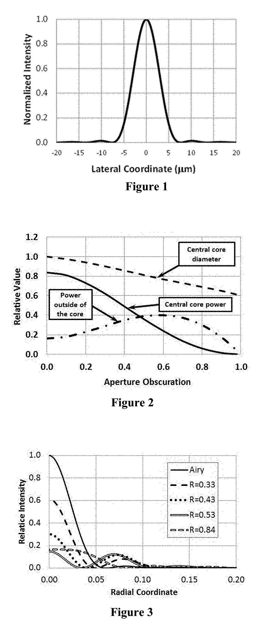
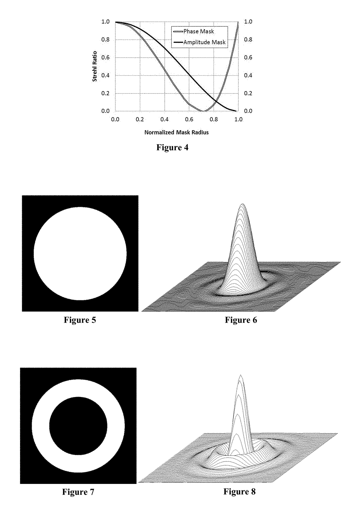
[0150]The first embodiment of the present invention is designed to transform PSF distributions of diffraction-limited optical systems with uniformly illuminated circular apertures, also known as Airy distributions. FIG. 24 shows the optical layout corresponding to the first embodiment of the present invention. It shows a diffraction-limited optical system 101 producing an Airy distribution in its back focal plane, as well as an optical system 102 for transforming the Airy distribution. The input intensity distribution and the Airy intensity distribution in the focal plane of a diffraction-limited optical system were shown earlier in FIGS. 5 and 6, respectively.
[0151]The optical system 102 in accordance with the first embodiment of the present invention transforms the PSF distribution of the diffraction-limited optical system 101 and produces the transformed optical field in the output plane 108. The optical system 102 contains a diffractive structure 103 placed within the focused op...
second embodiment
[0167]The second embodiment of the present invention is designed to transform PSF distributions of optical systems with central obscurations. This type of optical system is commonly found in reflective astronomical telescopes. The optical layout of the second embodiment of the present invention is presented in FIG. 40. It shows the optical system 200 with central obscuration producing a PSF distribution in the back focal plane, as well as the optical system 203 for transforming the PSF of the optical system 200 and producing the transformed optical field distribution in the output plane 206. The optical system 200 consists of a primary mirror 201 with a central opening and a secondary mirror 202 obstructing the aperture of the primary mirror 201. The uniformly illuminated aperture and the PSF intensity distribution of an optical system with central obscuration were shown in FIGS. 7 and 8, respectively.
[0168]In accordance with the second embodiment, the primary mirror 201 of the opti...
third embodiment
[0186]The third embodiment of the present invention is designed to transform optical field distributions produced by optical systems containing multiple spatially distributed apertures. The optical layout of the third embodiment is presented schematically in FIG. 62. The optical layout contains an optical system 300 composed of a segmented primary mirror and a secondary mirror 307. The primary mirror of the optical system 300 is comprised of six off-axis segments 301 through 306. Radiation collected by the segments 301 through 306 is reflected onto the secondary mirror 307 and is then redirected by the secondary mirror onto an image plane, where the PSF is produced. The image plane location depends on the location of an object or light source with respect to the optical system 300. For the purpose of the following discussion, we assume that objects are located at infinity, and therefore the image plane is located in the back focal plane of the optical system 300.
[0187]The optical la...
PUM
 Abstract
Description
Claims
Application Information
 - R&D
- Intellectual Property
- Life Sciences
- Materials
- Tech Scout
- Unparalleled Data Quality
- Higher Quality Content
- 60% Fewer Hallucinations
Browse by: Latest US Patents, China's latest patents, Technical Efficacy Thesaurus, Application Domain, Technology Topic, Popular Technical Reports.
© 2025 PatSnap. All rights reserved.Legal|Privacy policy|Modern Slavery Act Transparency Statement|Sitemap|About US| Contact US: help@patsnap.com


