
Antisqueezed light generator

a generator and generator technology, applied in waveguides, instruments, cladded optical fibres, etc., can solve the problems of insufficient compliance of conventional methods and high stability requirements of interferometers, and achieve the effects of improving communication security, increasing the bit error rate of eavesdroppers, and high stability

Inactive Publication Date: 2010-07-13
HITACHI LTD
View PDF2 Cites 6 Cited by
  • Summary
  • Abstract
  • Description
  • Claims
  • Application Information

AI Technical Summary

Benefits of technology

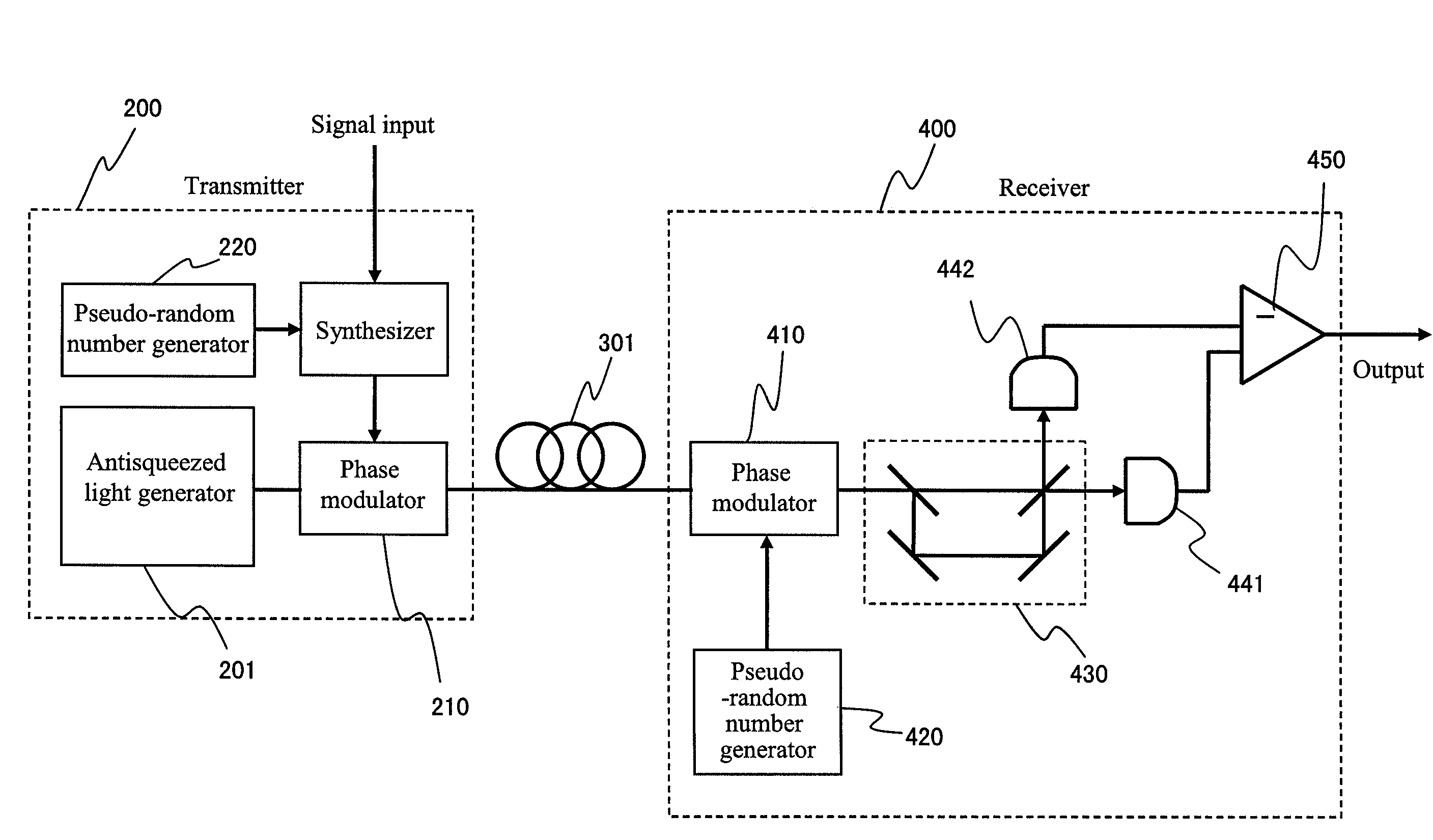
[0012]The secure optical communications using the antisqueezed light is intended to improve communication security by maintaining the amplitude fluctuation of the signal light at the level of regular optical communications, expanding only the phase fluctuation, and increasing the bit error rate of eavesdroppers. Because the bit error rate of the eavesdroppers increases with the ratio Δp / A0 of phase fluctuation Δp to amplitude A0, when the macroscopic light intensity (amplitude) of regular optical communications is used, the phase fluctuation will have to become a macroscopic size. Various methods which have been proposed and demonstrated in order to generate a squeezed state are ones for squeezing light by several dB with respect to vacuum fluctuation (consequently, antisqueezing it by several dB) and are not ones for obtaining macroscopic antisqueezing. Furthermore, conventional methods have used solid-state lasers or fiber lasers as pump light sources and also require an interferometer which requires high stability in some cases. For this reason, the conventional methods do not sufficiently comply with the requirements of the optical communications where maintenance-free operation and long-term reliability are essential. Consequently, the object of the present invention is to provide a method for generating the antisqueezed light that can provide sufficient Δp / A0 by using only regular optical communication components with high reliability. Furthermore, another object of the present invention is to satisfy specifications such as a repetition rate, inter-pulse coherence, and low jitter which are required in the optical communications.
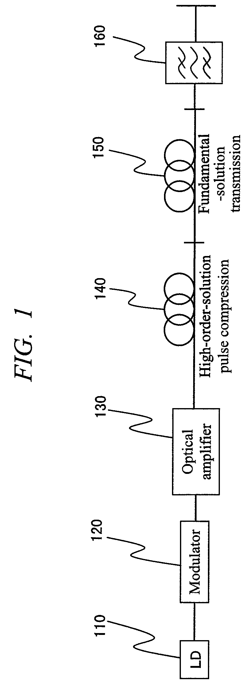
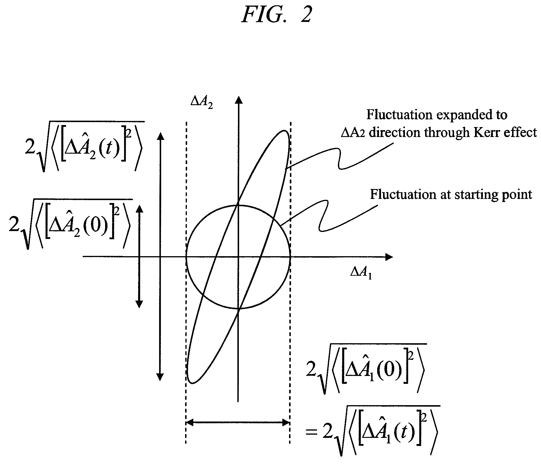
[0013]The Kerr effect of the optical fibers is used as a first principle to expand the fluctuation in the phase direction. Because this fluctuation-expanding effect increases with the light intensity, the required light intensity is inevitably increased. Because output light of a laser diode (LD) for optical communications is unable to obtain sufficient intensity even if it is amplified by an optical amplifier, the LD light is made into pulse forms by an intensity modulator and the peak intensity is reinforced by use of the high-order soliton compression effects of the optical fiber. If the pulse can be fiber-propagated while the reinforced peak power being maintained, the fluctuation in the phase direction can be increased by the Kerr effect. This can be achieved by introducing a second optical fiber and satisfying a fundamental soliton condition. Because optical fibers are long, sufficiently antisqueezed light in the phase direction can be obtained through an integration effect. The present means is configured only by components for optical communications and can satisfy specifications required for the optical communications.
[0014]The above-mentioned means is configured all only by components for regular optical communications and not only satisfy the requirements for the long-term reliability but also achieve the requirements for the maintenance-free operation. Furthermore, since the LD performs a continuous-wave (cw) operation, the inter-pulse coherence is also secured and since the repetition rate is determined only by a modulation rate of the intensity modulator, the repetition rate is variable and has low jitter with high stability. Therefore, the sufficiently antisqueezed light, which satisfies the specifications required in optical communications, can be obtained and the optical communications with security guaranteed from the viewpoint of the physical laws become feasible also at the level of macroscopic light intensity.

Problems solved by technology

Furthermore, conventional methods have used solid-state lasers or fiber lasers as pump light sources and also require an interferometer which requires high stability in some cases.
For this reason, the conventional methods do not sufficiently comply with the requirements of the optical communications where maintenance-free operation and long-term reliability are essential.

Method used


Image

  • Antisqueezed light generator
  • Antisqueezed light generator
  • Antisqueezed light generator

Examples


first embodiment

[0030]FIG. 1 is a block diagram which shows one embodiment of the present invention. Output light from a cw LD 110 is converted into pulsed light by an intensity modulator 120, amplified by an optical amplifier 130, and transmitted to a single-mode fiber 140 which exhibits negative group-velocity dispersion at the operating wavelength of the LD 110. The pulsed light transmitted in the optical fiber is subject to a wavelength-dependent dispersion specific to the fiber and the light intensity-dependent Kerr effect. At an appropriate light intensity, the dispersion effect and the Kerr effect are balanced and the pulsed light is transmitted in the fiber with the pulse waveform being maintained. This is a state called the fundamental soliton. When the light intensity is increased from this soliton condition, a high-order soliton state is generated and a pulse width is varied in a period called the soliton period. If the transmission in the fiber 140 is terminated at a spot where the puls...

second embodiment

[0064]Single mode fibers are basically formed circularly symmetric, but has slight birefringence caused by strain, twist, or bend. Because of this birefringence, the polarization of the transmitted light is varied, whereby the effective Kerr effect is slightly changed. If a polarization controller 141 is installed ahead of the input of the fiber 140 as shown in FIG. 6, it is possible to control the effective Kerr effect and to obtain the optimum condition for high-order soliton compression. Similarly, if a polarization controller 151 is installed ahead of the input of the fiber 150, it is possible to control the effective Kerr effect in the fiber 150 and to get the optimum condition in generating the antisqueezed light.

third embodiment

[0065]In the first and second embodiments, one-directional configurations are adopted and they are advantageous from a viewpoint of their simple configuration. However, for the fiber 150, the length of 10 to several tens km is typically required, which is rather uneconomical. FIG. 7 shows a round-trip transmission configuration for the fiber 150. The configuration up to the fiber 140 is the same as that of the first Embodiment. After the fiber 140, the light first passes an isolator 145. This is needed because slight returned light is present in the round-trip configuration. Next, the light is controlled to linearly polarized light by a polarization controller 146 and passes a polarizing beam splitter 147. If the transmission line from the LD 110 to the polarizing beam splitter 147 is connected with polarization-maintaining fibers, the polarization controller 146 can be omitted. After passing the polarizing beam splitter 147, the light is transmitted in the fiber 150, is converted i...


PUM

PropertyMeasurementUnit
lengthaaaaaaaaaa
lengthaaaaaaaaaa
lengthaaaaaaaaaa

Abstract

An antisqueezed light generator system is built with only the components for optical communications with long-term reliability. A cw-LD light is made pulses by an intensity modulator and amplified by an optical amplifier. The amplified optical pulses are made short by high-order soliton pulse compression effect at a first optical fiber and peak power is increased. A fluctuation is expanded in a phase direction through propagation in a second optical fiber. Because an initial fluctuation is amplified by the optical amplifier, the fluctuation expanded in the phase direction is increased to the extent of the amplification and sufficient antisqueezing strength can be obtained.

Description

CROSS-REFERENCE TO RELATED APPLICATION[0001]The present application claims priority from Japanese patent application No. JP 2006-173286 filed on Jun. 23, 2006, the content of which is hereby incorporated by reference into this application.TECHNICAL FIELD OF THE INVENTION[0002]The present invention relates to an antisqueezed light generator and in particular to quantum communications, quantum cryptography, and optical communications.BACKGROUND OF THE INVENTION[0003]A request for confidentiality in communications has been an eternal theme from ancient times through the future, and in the recent network society, the request has been secured by development of cryptology. Security of a public key cryptosystem etc. which are presently prevalent is based on the fact that it takes unrealistically long time to decipher the ciphertext, but since computer technologies continue advancing steadily, the security of the public key cryptosystem etc. is not always promised into the future. On the ot...

Claims


Application Information

Patent Timeline
Patent Type & Authority Patents(United States)
IPC IPC(8): G02B6/00G02F1/35H04B10/00H04B10/508H04B10/516H04B10/548H04B10/58H04B10/61H04B10/70H04L9/12
CPCH04B10/508H04B10/70Y10S385/901
Inventor TOMARU, TATSUYA
Owner HITACHI LTD
Learn More