Projector having an electro-optical device encased in a heat dissipating mounting case
a technology of electro-optical devices and mounting cases, which is applied in the field of projectors, can solve the problems of reducing cooling efficiency, unable to provide satisfactory cooling effect, and difficulty in transmitting heat to the cooling air, and achieves the effect of efficient cooling and prolonging the life of the optical par
- Summary
- Abstract
- Description
- Claims
- Application Information
AI Technical Summary
Benefits of technology
Problems solved by technology
Method used
Image
Examples
first embodiment
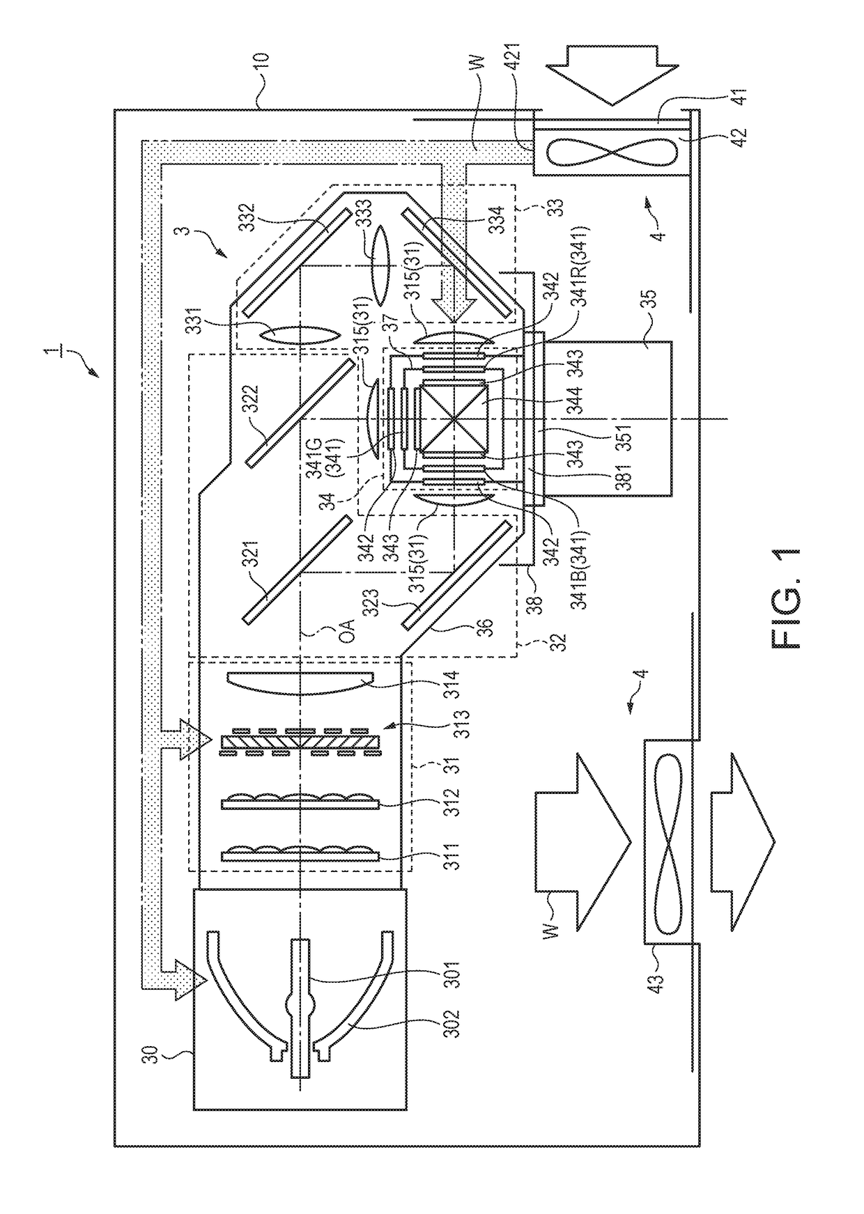
[0040]FIG. 1 diagrammatically shows a schematic configuration of a projector 1 according to a first embodiment. FIG. 1 is a diagrammatic view in which the internal configuration of the projector 1 installed on a desktop is viewed from above. FIG. 1 further diagrammatically shows a cooling mechanism 4. The schematic configuration and operation of the projector 1 according to the present embodiment will be described with reference to FIG. 1.
[0041]In the following drawings including FIG. 1, it is assumed for ease of description that the traveling direction of light outputted from a light source apparatus 30 and traveling along an illumination optical axis OA is a forward direction (front side), and that the direction opposite the forward direction is a rearward direction (rear side). The front side corresponds to the direction in which light is incident on an optical part and exits out of the optical part, and the rear side corresponds to the direction opposite the direction correspond...
second embodiment
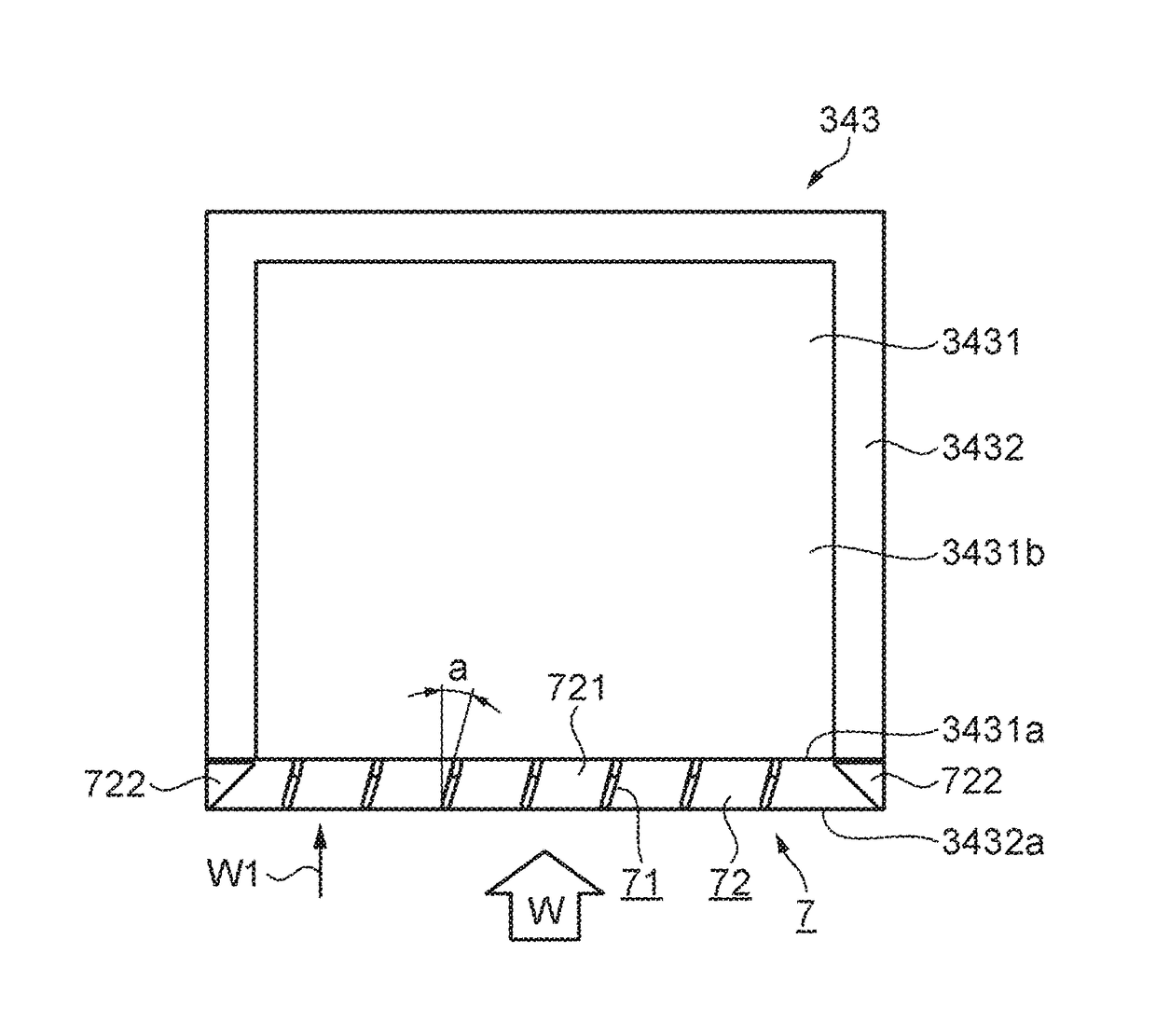
[0086]FIGS. 6A to 6C show that each of the light-exiting-side polarizers 343 is provided with a turbulence generator 7 according to a second embodiment. FIG. 6A is a perspective view, FIG. 6B is a plan view, and FIG. 6C is a side view viewed from the lower side. The turbulence generator 7 according to the present embodiment is disposed on the light incident side of the light-exiting-side polarizer 343 on which the modulated light outputted from the liquid crystal panel 341 is incident.
Configuration of Light-Exiting-Side Polarizers 343
[0087]Each of the light-exiting-side polarizers 343 is formed of a polarizer main body 3431, which is formed of a film-shaped organic polarizer, and a light transmissive substrate (transparent glass plate 3432 in the present embodiment) to which the light exiting side of the polarizer main body 3431 is attached.
Configuration of Turbulence Generator 7
[0088]The turbulence generator 7 according to the present embodiment is formed of a plate-shaped inclined...
third embodiment
[0103]FIGS. 9A to 9C show that each light-exiting-side polarizer 343A is provided with a turbulence generator 7A according to a third embodiment. FIG. 9A is a perspective view, FIG. 9B is a plan view, and FIG. 9C is a side view viewed from the lower side. The turbulence generator 7A according to the present embodiment is disposed on the light incident side of the light-exiting-side polarizer 343A on which the modulated light outputted from the liquid crystal panel 341 is incident.
[0104]The present embodiment differs from the second embodiment in that a transmissive, inorganic polarizer as each of the light-exiting-side polarizers 343 is provided with the turbulence generator 7A. In the following description, the light-exiting-side polarizers 343 in the second embodiment are replaced with the light-exiting-side polarizers 343A.
Configuration of Light-Exiting-Side Polarizers 343A
[0105]Each of the light-exiting-side polarizers 343A in the present embodiment has a configuration having a ...
PUM
 Abstract
Description
Claims
Application Information
 - R&D
- Intellectual Property
- Life Sciences
- Materials
- Tech Scout
- Unparalleled Data Quality
- Higher Quality Content
- 60% Fewer Hallucinations
Browse by: Latest US Patents, China's latest patents, Technical Efficacy Thesaurus, Application Domain, Technology Topic, Popular Technical Reports.
© 2025 PatSnap. All rights reserved.Legal|Privacy policy|Modern Slavery Act Transparency Statement|Sitemap|About US| Contact US: help@patsnap.com


