Imaging device and imaging system
a technology which is applied in the field of imaging device and imaging system, can solve the problem that the autofocus function cannot be achieved in sufficient degree, and achieve the effect of achieving sufficient autofocus function
- Summary
- Abstract
- Description
- Claims
- Application Information
AI Technical Summary
Benefits of technology
Problems solved by technology
Method used
Image
Examples
first embodiment
[0031]An imaging device and a method for driving the same according to a first embodiment of the present invention will be described with reference to FIGS. 1 to 7B.
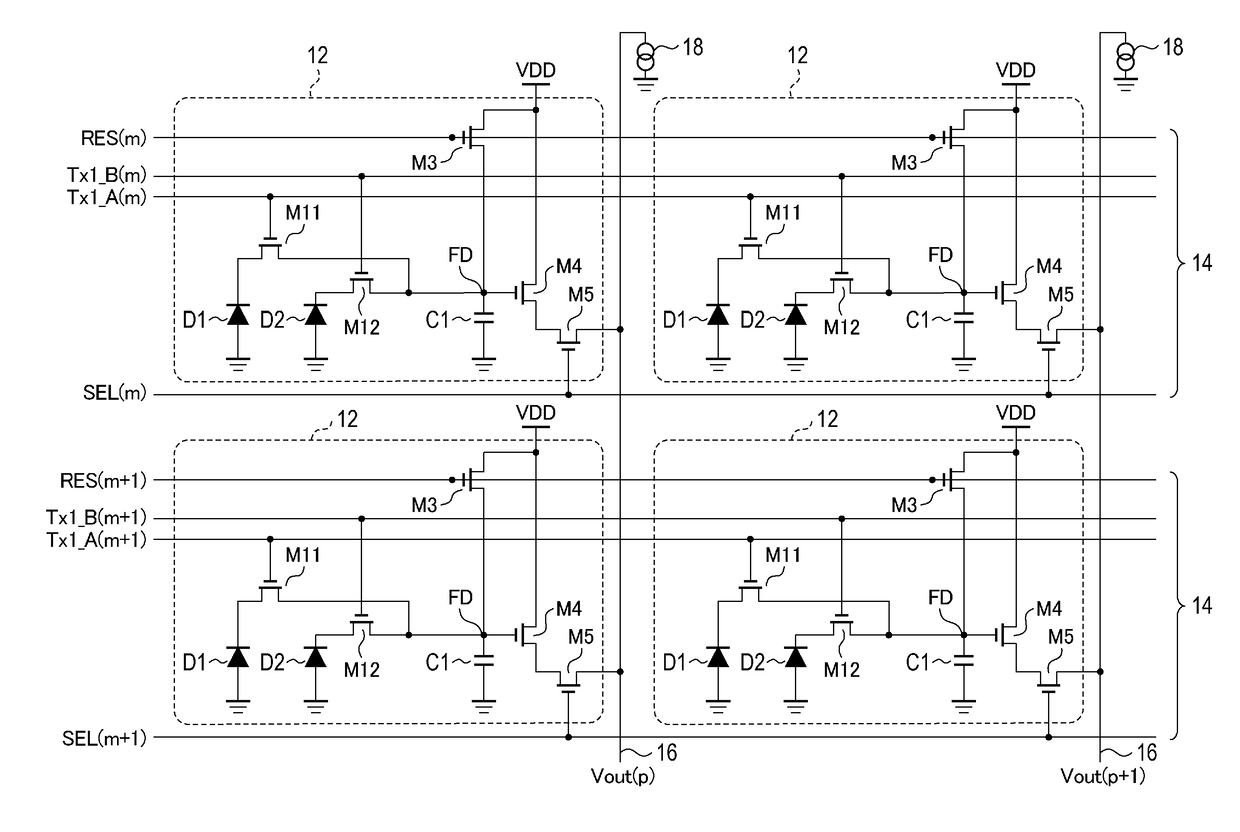
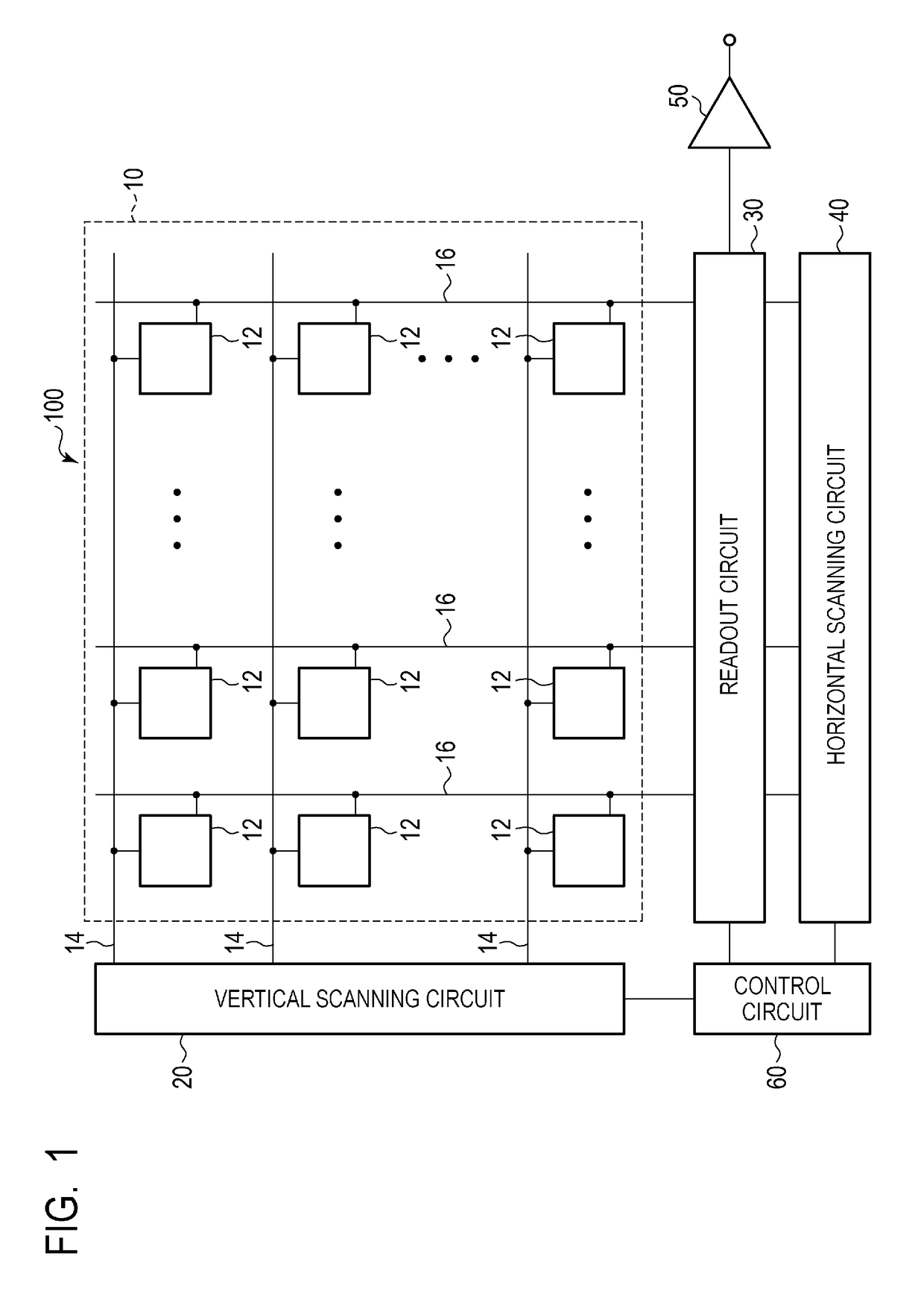
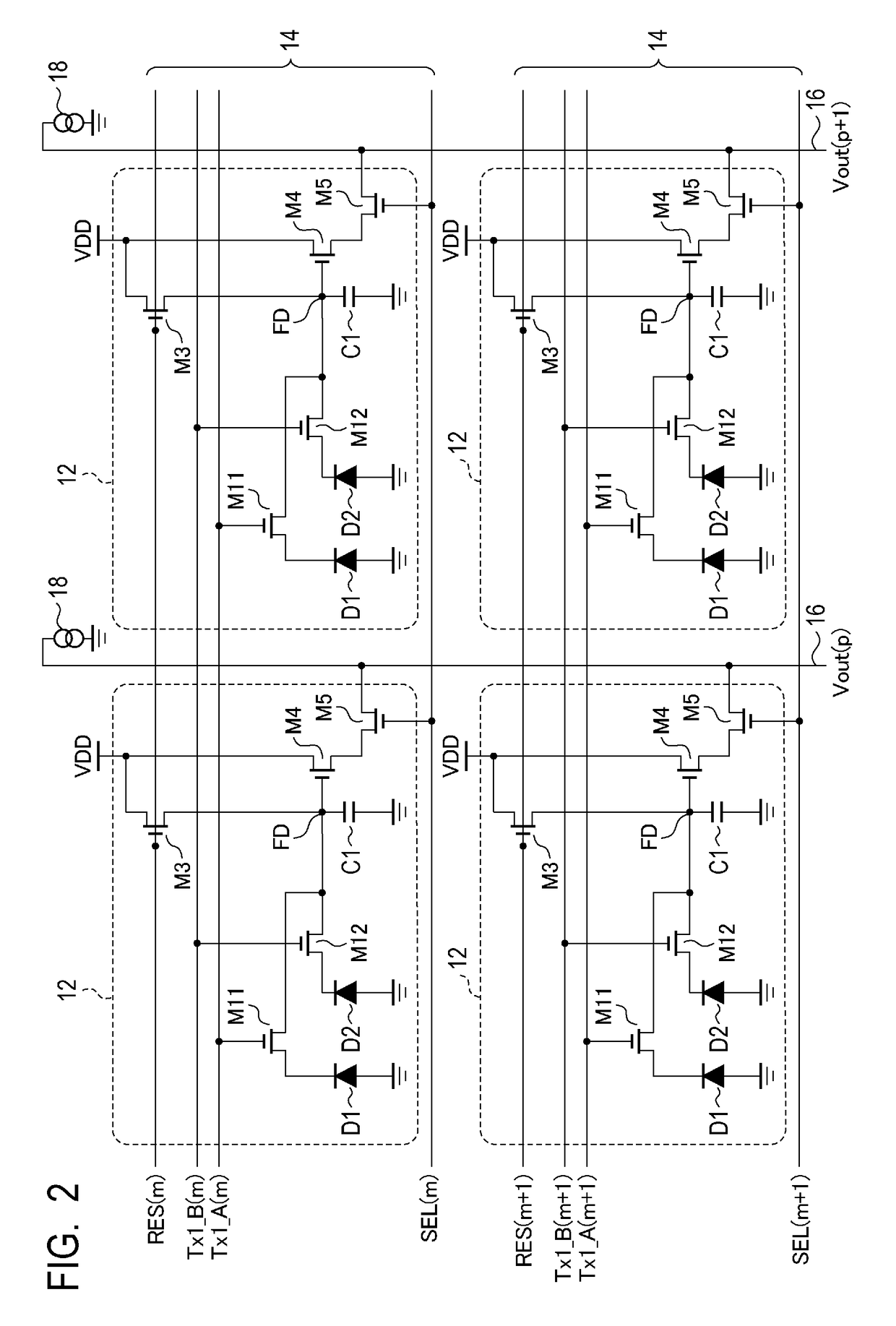
[0032]FIG. 1 is a block diagram illustrating the schematic configuration of the imaging device according to the present embodiment. FIG. 2 is a diagram illustrating an example of configuration of a pixel circuit of the imaging device according to the present embodiment. FIG. 3 is a schematic diagram illustrating an example of a plan-view layout of a pixel array unit of the imaging device according to the present embodiment. FIG. 4 is a cross-sectional view illustrating an example of a pixel structure in the imaging device according to the present embodiment. FIGS. 5A and 5B are schematic diagrams illustrating a method for driving the imaging device according to the present embodiment. FIGS. 6A to 7B are timing charts illustrating the method for driving the imaging device according to the present embodiment.
[0033]First, t...
second embodiment
[0079]An imaging device and a method for driving the same according to a second embodiment of the present invention will be described with reference to FIGS. 8 to 12. Components that are the same as those in the imaging device according to the first embodiment illustrated in FIGS. 1 to 7B are denoted by the same reference signs as those used in the first embodiment, and are either not described or described only briefly.
[0080]FIG. 8 is a diagram illustrating an example configuration of pixel circuits of the imaging device according to the present embodiment. FIG. 9 is a schematic diagram illustrating an example plan-view layout of a pixel array unit of the imaging device according to the present embodiment. FIG. 10 is a cross-sectional view illustrating an example pixel structure in the imaging device according to the present embodiment. FIG. 11 is a schematic view illustrating a method for driving the imaging device according to the present embodiment. FIG. 12 is a timing chart ill...
third embodiment
[0098]An imaging device and a method for driving the same according to a third embodiment of the present invention will be described with reference to FIGS. 13 to 16. Components that are the same as those in the imaging devices according to the first and second embodiments illustrated in FIGS. 1 to 12 are denoted by the same reference signs as those used in the first and second embodiments, and are either not described or described only briefly.
[0099]FIG. 13 is a diagram illustrating an example configuration of pixel circuits of the imaging device according to the present embodiment. FIG. 14 is a schematic diagram illustrating an example plan-view layout of a pixel array unit of the imaging device according to the present embodiment. FIG. 15 is a schematic view illustrating a method for driving the imaging device according to the present embodiment. FIG. 16 is a timing chart illustrating the method for driving the imaging device according to the present embodiment.
[0100]First, a des...
PUM
 Abstract
Description
Claims
Application Information
 - R&D
- Intellectual Property
- Life Sciences
- Materials
- Tech Scout
- Unparalleled Data Quality
- Higher Quality Content
- 60% Fewer Hallucinations
Browse by: Latest US Patents, China's latest patents, Technical Efficacy Thesaurus, Application Domain, Technology Topic, Popular Technical Reports.
© 2025 PatSnap. All rights reserved.Legal|Privacy policy|Modern Slavery Act Transparency Statement|Sitemap|About US| Contact US: help@patsnap.com


