Eureka AIR delivers breakthrough ideas for toughest innovation challenges, trusted by R&D personnel around the world.

SCR Device with valve arrangement

Active Publication Date: 2018-07-17
ROECHLING AUTOMOTIVE SE & CO KG
View PDF11 Cites 1 Cited by
  • Summary
  • Abstract
  • Description
  • Claims
  • Application Information

AI Technical Summary

Benefits of technology

[0004]In this case an object of the present invention is to modify the above-mentioned SCR device in such a way that reducing liquid can flow at least in the flow direction from the tank to the injection device only when the feed pump is in operation. When the feed pump is not in operation, a flow of reducing liquid in the liquid conduit should be prevented at least in said direction from the tank to the injection device. In this way a very precise injection control can be achieved. Moreover, this simplifies the dismantling of the SCR device, since in this way an undesirable leakage of reducing liquid from the SCR device can be prevented or at least greatly limited in terms of quantity.
[0014]Therefore, in order to provide an SCR device according to the invention with the lowest possible expenditure on apparatus and construction, it is preferable if the feed pump is a bidirectionally operating pump that is designed to produce both the pressure difference that causes the injection flow and also the pressure difference that causes the return flow. Thus, by reversal of the conveying direction at the feed pump, both the injection flow and also the return flow through one and the same feed pump can be produced. Therefore, just one liquid conduit can be sufficient.
[0025]Due to the arrangement of the valve arrangement discussed above in the liquid conduit of the SCR device, after emptying of the liquid conduit by generation of a return flow the liquid conduit can be closed in an advantageous manner at the valve arrangement, for example in order to replace conduit portions between the valve arrangement and the injection device or between the valve arrangement and the feed pump. For this purpose, in an advantageous further embodiment of the present invention it can be provided that on the injection device side of the valve arrangement, preferably directly on the valve arrangement, the liquid conduit can be properly separated, preferably from a valve housing of the valve arrangement. “Proper separation” means non-destructive separation, for example by the provision of a releasable screwed or / and plug-in connection of the individual liquid line portions to one another.

Problems solved by technology

On the other hand, if the feed pump is switched off, a corresponding pressure difference no longer exists, so that at least the injection flow can no longer override the valve arrangement.

Method used


Image

  • SCR Device with valve arrangement
  • SCR Device with valve arrangement
  • SCR Device with valve arrangement

Examples


Embodiment Construction

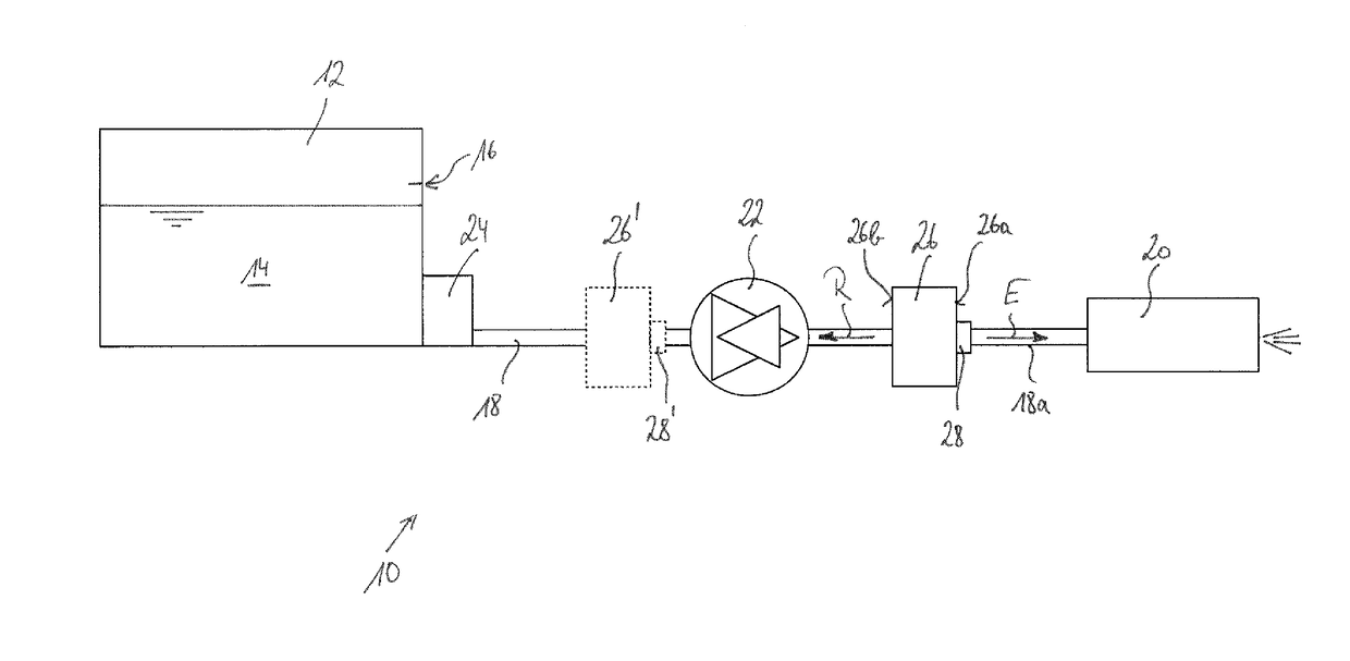
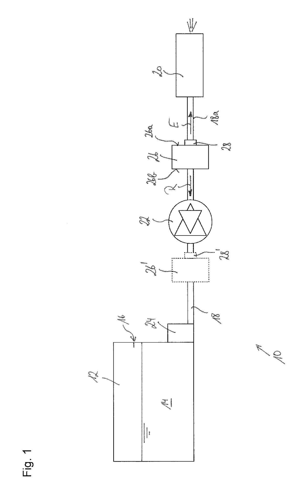
[0030]Referring now to the drawings wherein the showings are for the purpose of illustrating preferred and alternative embodiments of the invention only and not for the purpose of limiting the same, FIG. 1 shows an SCR device according to certain aspects of the invention that is designated generally by 10. The SCR device, which serves for reduction of nitrogen oxides in the exhaust gas of an internal combustion engine of a motor vehicle, comprises a tank 12, in which reducing liquid 14, for example aqueous urea solution, can be introduced up to a rated filling level 16 according to regulations. A filling line and the like is not shown in FIG. 1, since it does not play any further role for the SCR device according to the present invention.

[0031]The reducing liquid 14 can be conveyed by means of a liquid conduit 18 to an injection device 20, where it is injected into an exhaust gas from an internal combustion engine in an exhaust gas system that is not shown in FIG. 1.

[0032]In order t...


PUM


Abstract

An SCR device for a motor vehicle, comprising a tank for storing reducing liquid, an injection device for injection of the reducing liquid into an exhaust gas system of a motor vehicle, a liquid conduit for delivering reducing liquid from the tank to the injection device, a feed pump for conveying reducing liquid in the conduit, and a valve arrangement in the conduit, the valve arrangement designed to interrupt an injection flow in the conduit when the tank-side pressure is greater, than the injection device-side pressure in the conduit by less than an injection threshold value, and to allow the injection flow to pass when the tank-side pressure is greater by at least the injection threshold, the valve arrangement designed to interrupt a return flow in the conduit from the injection device to the tank when the injection device-side pressure is greater than the tank-side pressure by less than a return threshold value, and to allow the return flow to pass through when the injection device-side pressure is greater than the tank-side pressure in the conduit, by at least the return threshold value, the injection threshold value being greater than the return threshold value.

Description

[0001]The present invention relates to an SCR device for a motor vehicle, comprising a tank for storing reducing liquid, in particular aqueous urea solution, an injection device for injection of the reducing liquid into an exhaust gas system of a motor vehicle, a liquid conduit for delivering reducing liquid from the tank to the injection device, a feed pump for conveying reducing liquid in the liquid conduit, and a valve arrangement present in the liquid conduit.BACKGROUND OF THE INVENTION[0002]A generic SCR device is known for example from DE 10 2007 028 480 A1. This known SCR device has a valve arrangement at the upstream end of the liquid conduit, wherein the valve arrangement is designed to close the liquid conduit when a filling level of the reducing liquid in the tank reaches or falls below a minimum filling level.[0003]SCR devices are generally known in order, by injection of a reducing liquid, as a rule aqueous urea solution, into the exhaust gas system of a motor vehicle, ...

Claims


Application Information

Patent Timeline
Patent Type & Authority Patents(United States)
IPC IPC(8): F01N3/00F01N3/20
CPCF01N3/2066F01N2610/02F01N2610/1433Y02T10/24F01N2610/1473F01N2900/1808Y02A50/2325F01N2610/1453F01N3/206F01N2610/14Y02A50/20Y02T10/12
Inventor CHINI, FABRIZIOMARINI, LUCA
Owner ROECHLING AUTOMOTIVE SE & CO KG
Why Eureka
Eureka Blog
Learn More