Collaborative robot

a robot and collaborative technology, applied in the field of collaborative robots, can solve the problems of reducing effective mass and reflected inertia, and achieve the effect of higher speeds

Active Publication Date: 2018-07-24
PRECISE AUTOMATION INC +2
View PDF55 Cites 19 Cited by
  • Summary
  • Abstract
  • Description
  • Claims
  • Application Information

AI Technical Summary

Benefits of technology

[0008]In accordance with an aspect of the invention, a robot is provided that may operate around humans, e.g., the robot may be configured to operate alongside human beings according to ISO_TS 15066 2016 regulations, while achieving higher speeds than other collaborative approaches. In one arrangement, the robot may include four or more degrees of freedom, e.g., the robot may include multiple links or other components that are joined together such that each link can pivot or otherwise move in relation to a respective axis relative to the link or other component to which the link is joined. Movement of links or other robot components relative to at least three of the axes (or degrees of freedom) may be driven by a motor and drive train that has a low drive ratio, e.g., having a ratio of 25:1 or less, and / or may be back-drivable (i.e., the rotor of the drive motor may be rotated or otherwise moved by exerting force on the driven robot link or other part). In some cases, employing a drive ratio of less than 10:1 for at least three axes, and particularly for at least three major axes of the robot, may provide particular advantages.
[0009]In one embodiment, the robot may have a base that is fixed relative to ground or another structure, and an arm assembly may be movable relative to the base along an arm assembly axis. In one example, the arm assembly may be movable along a vertical direction relative to the base, and may be cantilevered relative to the base. The arm assembly may include a first link that is pivotable about a first axis relative to the base, and a second link that is pivotable about a second axis relative to the first link. Movement of the arm assembly, the first link and the second link in relation to their respective axes may be driven by a motor and drive train that has a low drive ratio of 25:1 or less and / or that is back-drivable. (In the case of a drive ratio of 1:1, the drive train may be very simple and include a connection of a motor shaft to the respective part, such as a direct connection of a drive motor shaft to the first link. However, other drive train arrangements are possible that have a drive ratio of 1:1 and yet include multiple components.) By employing a low drive ratio of 25:1 or less for three axes or degrees of freedom, the robot may have significantly reduced reflected inertia, and thus reduced effective mass, as compared to robotic structures that employ higher ratio drive trains. This may enable the collaborative robot to operate safely at higher speeds in the presence of humans than would otherwise be possible.
[0010]In some embodiments, the three degrees of freedom of the robot that employ low ratio drive trains for movement may be the major or “first” three degrees of freedom of the robot. The “first” three degrees of freedom (or movement axes) in this case are determined as the three degrees of freedom physically or functionally nearest the robot base. These “first” three degrees of freedom may have the greatest impact or influence on the speed and distance of movement of the robot end effector or other end portion of the robot since they are often furthest from the end effector and these degrees of freedom typically provide the greatest torque since they need to accelerate the largest inertias. Thus, providing low ratio drive trains with their reduced reflected inertias for the “first” three degrees of freedom (or movement axes) may have the greatest influence in terms of reducing potential collision forces. Of course, low ratio drive trains may be used for other degrees of freedom that are “further” from the robot base.

Problems solved by technology

By employing a low drive ratio of 25:1 or less for three axes or degrees of freedom, the robot may have significantly reduced reflected inertia, and thus reduced effective mass, as compared to robotic structures that employ higher ratio drive trains.

Method used


Image

  • Collaborative robot
  • Collaborative robot
  • Collaborative robot

Examples


Embodiment Construction

[0029]It should be understood that aspects of the invention are described herein with reference to certain illustrative embodiments and the figures. The illustrative embodiments described herein are not necessarily intended to show all aspects, but rather are used to describe a few illustrative embodiments. Thus, aspects are not intended to be construed narrowly in view of the illustrative embodiments. In addition, it should be understood that certain features disclosed herein might be used alone or in any suitable combination with other features.

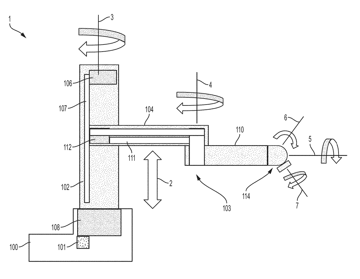
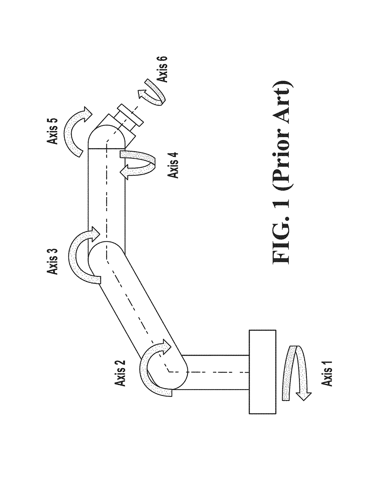
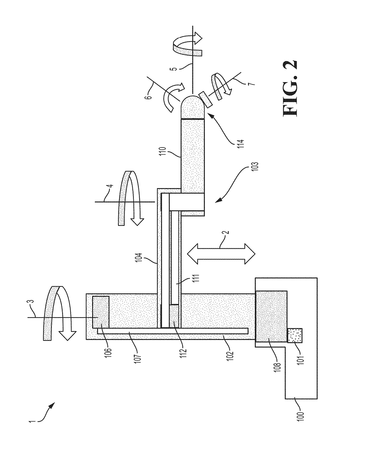
[0030]The safe operating speed for a collaborative robot is determined by the kinetic energy of the moving mass (which is equal to ½ mv2), the motor torque applied during the collision, the compliance (stiffness) of the robot and the region of the person where the robot strikes. The moving mass is composed of the robot payload, the robot structure, and an equivalent mass that represents the forward reflected inertias of the motor rotors and...


PUM


Abstract

A collaborative robot employs low ratio drives for three or more axes of movement, such as three primary axes. An arm assembly may be mounted to a support for movement along a vertical linear axis, and the arm assembly may include first and second arm links that are each rotatable about vertical axes, e.g., such that the arm links move in a horizontal plane. Low ratio drives may be used for movement along the vertical linear axis and the rotary axes for the first and second arm links. Feedforward and feedback control may be employed to control the movement of the arm assembly and arm links, and feedback torque components may be limited to 25% or less of the maximum drive torque.

Description

CROSS REFERENCE TO RELATED APPLICATION[0001]This application is a continuation of U.S. application Ser. No. 15 / 618,525, filed Jun. 9, 2017 which is hereby incorporated by reference in its entirety.BACKGROUND[0002]Until recently all industrial robots installed in factories were separated from people by safety barriers and interlocks to prevent the robots from colliding with a human and possibly causing injury. Large robots can carry payloads of hundreds of kilograms and are therefore potentially very dangerous due to the masses involved. However, even small assembly robots, which often operate at high tool speeds of 7-10 meters per second, have enough energy to seriously injure humans though their payloads are typically 3 kg or less.[0003]Recently there has been growing interest in allowing robots to work safely next to people in the same working volume without the need for expensive and cumbersome safety screens. This class of robots is referred to in the industry as “Collaborative ...

Claims


Application Information

Patent Timeline
Patent Type & Authority Patents(United States)
IPC IPC(8): G05B19/04B25J13/08B25J9/10B25J9/16B25J9/12G05B19/18
CPCB25J9/1676B25J9/12B25J9/104B25J13/085G05B2219/40202G05B2219/40201
Inventor CARLISLE, BRIANSHIMANO, BRUCE
Owner PRECISE AUTOMATION INC
Why Eureka
Try Eureka