
Contact lens with metered liquid system

a liquid system and contact lens technology, applied in the field of contact lens with metered liquid system, can solve the problems of progressively complicated daily, bi-weekly or monthly dosing over two or more years, ineffective delivery mode, and less than 10% absorption in the eye,

Active Publication Date: 2018-07-24
CALIFORNIA INST OF TECH +1
View PDF14 Cites 6 Cited by
  • Summary
  • Abstract
  • Description
  • Claims
  • Application Information

AI Technical Summary

Benefits of technology

The present invention relates to devices that can deliver fluids and drugs to specific parts of the body in a controlled and targeted manner. These devices can include contact lenses, intraocular lenses, and other implantable or non-implantable pumps. The devices can use micromachined channels and valves that are mechanically actuated, controlled by external pressure or an electronic actuator. The devices can also include a one-way valve, a metering volume with a predetermined capacity for a therapeutic liquid, and a pressure regulator. The devices can be used for the delivery of therapeutic fluids and drugs to treat various medical conditions.

Problems solved by technology

This mode of delivery, however, is very inefficient, with sometimes less than 10% absorption in the eye of the medicine from the eye drops.
As implantable devices of varying sizes, dosing requirements, and implant locations become available, the reliable delivery of drugs / fluids over long periods of time (i.e. daily, bi-weekly or monthly dosing over two or more years become progressively complicated.
Existing medical equipment actuation and metering systems would be difficult, if not impossible, to miniaturize into a scale that is implantable or that can fit into a contact lens.
The functionality of many slow response actuation systems (i.e. electro-osmosis electrolysis) based pumps are limited in the fact that for temporally separated doses, each successive dose requires more time and / or power to complete.
That is, slow response actuation systems require electrical power over long periods of time—electrical power that drains batteries.

Method used


Image

  • Contact lens with metered liquid system
  • Contact lens with metered liquid system
  • Contact lens with metered liquid system

Examples


Embodiment Construction

[0058]Generally, therapeutic medical liquid dispensing devices are described herein. Particularly described are exemplary contact lens devices to treat dry eyes by supplying a controlled volume of fluid over time to the eye. The devices dispenses a reliable amount of fluid to the eye over extended periods of time. In other embodiments, other fluids delivered can include anti-infective agents, anti-inflammatory drugs, medication for chronic immunomodulation, glaucoma medication, or other known eye medications.

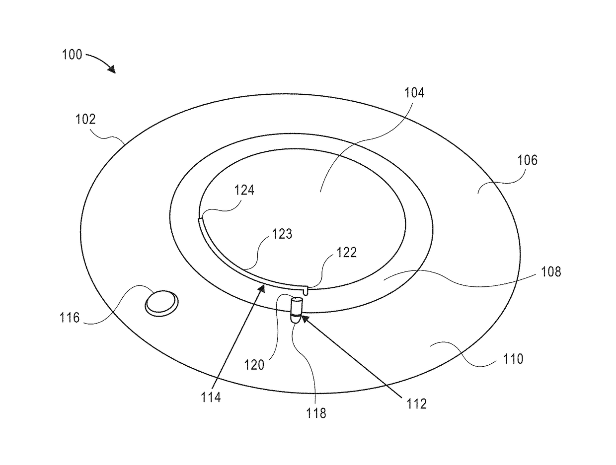
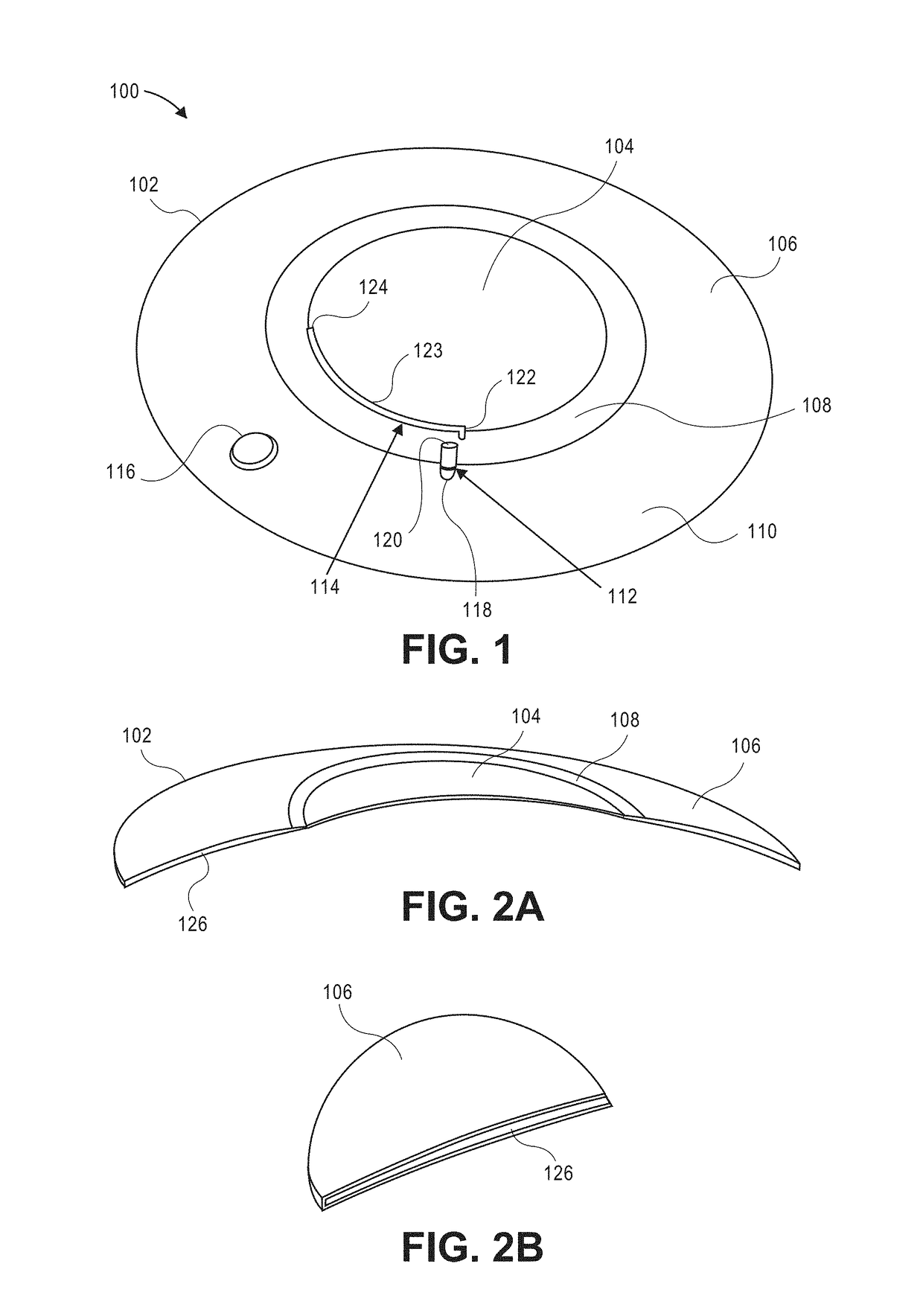
[0059]FIG. 1 illustrates a perspective view of a contact lens in accordance with an embodiment. Contact lens 100 includes a body 102, a transparent optical zone 104, and an annular periphery 110. The annular periphery 110 further includes a metering volume 108 and a therapeutic liquid storage reservoir 106. Liquid travels from the reservoir 106 through an opening 118 of a one-way valve 112 and out an outlet 120 into the metering volume 108. From the metering volume 108, the liqu...


PUM


Abstract

A contact lens fluid delivery device having a liquid reservoir connected to a channel with a flow regulator is described. Other eye hydration and variable dioptric power contact lenses are described herein. Also described are implantable liquid delivery apparatuses having a liquid storage reservoir connected to a channel with a flow regulator. These devices and apparatuses are useful for specific, targeted delivery of therapeutic liquids within a subject. In some embodiments, the devices incorporate actuation chambers which provide a driving force releasing the fluid into the targeted area e.g., the eye. The actuation chambers described herein can contain phase change materials or osmotic chambers or a combination thereof to drive the release of fluid.

Description

CROSS-REFERENCES TO RELATED APPLICATIONS[0001]This application claims the benefit of U.S. Provisional Application No. 62 / 152,518, filed Apr. 24, 2015, U.S. Provisional Application No. 62 / 131,476, filed Mar. 11, 2015, and U.S. Provisional Application No. 62 / 064,339, filed Oct. 15, 2014, the contents of which are hereby incorporated in their entireties for all purposes.STATEMENT AS TO RIGHTS TO INVENTIONS MADE UNDER FEDERALLY SPONSORED RESEARCH AND DEVELOPMENT[0002]NOT APPLICABLEBACKGROUND[0003]Generally, embodiments of the present invention related devices for administration of a therapeutic agent (e.g., medicament, drugs, saline, etc.) to a particular part of a patient's body.[0004]One example of targeted delivery to a part of a patient's body is the eye using a contact lens.[0005]The most common treatment for various eye conditions is through topical application of ophthalmic solutions or eye drops. This method of fluid delivery to the eye accounts for 90% of all the ophthalmic med...

Claims


Application Information

Patent Timeline
Patent Type & Authority Patents(United States)
IPC IPC(8): G02C7/00G02C7/02G02C7/04G02C7/08G02C7/06A61K9/00
CPCG02C7/049G02C7/04G02C7/085G02C7/041A61K9/0051
Inventor TAI, YU-CHONGSCIANMARELLO, NICHOLAS E.DEBOER, CHARLES M. T.HUMAYUN, MARK S.
Owner CALIFORNIA INST OF TECH
Learn More