Interference signal cancellation apparatus and method

a signal cancellation and interference technology, applied in the field of communication technologies, can solve problems such as communication system instability, interference suppression and cancellation, and increase a bit error ra

Active Publication Date: 2018-07-24
HUAWEI TECH CO LTD
View PDF9 Cites 0 Cited by
  • Summary
  • Abstract
  • Description
  • Claims
  • Application Information

AI Technical Summary

Benefits of technology

[0006]Based on this, an interference signal cancellation apparatus is provided, to resolve the foregoing problem of insufficient reliability caused by the interference cancellation method in the conventional technology.

Problems solved by technology

A key technical problem in radio and microwave communication is interference suppression and cancellation.
However, although the transmit antenna and the receive antenna are physically different antennas, the transmit antenna and the receive antenna are generally relatively close to each other because a physical cabling layout of the communications system is limited.
Therefore, in a same communications system, a transmitting link generally interferes with a receiving link, and a signal transmitted by the transmitting link is an interference signal for the receiving link.
However, it is found by means of research that the interference signal cancellation apparatus and method in the conventional technology have at least the following problem: When performing interference cancellation on a received signal according to a cancellation reference signal, an interference cancellation unit generally needs to perform a parameter adjustment operation such as time shift, phase shift, or attenuation on the cancellation reference signal, so that the cancellation reference signal corresponds to a component of an interference signal in the received signal.
Because an excessively strong interference signal may increase a bit error rate, communication is interrupted and consequently a communications system becomes unstable.

Method used


Image

  • Interference signal cancellation apparatus and method
  • Interference signal cancellation apparatus and method
  • Interference signal cancellation apparatus and method

Examples


Embodiment Construction

[0022]The following clearly describes the technical solutions in the embodiments of the present disclosure with reference to the accompanying drawings in the embodiments of the present disclosure. Apparently, the described embodiments are merely some but not all of the embodiments of the present disclosure. All other embodiments obtained by a person of ordinary skill in the art based on the embodiments of the present disclosure without creative efforts shall fall within the protection scope of the present disclosure.

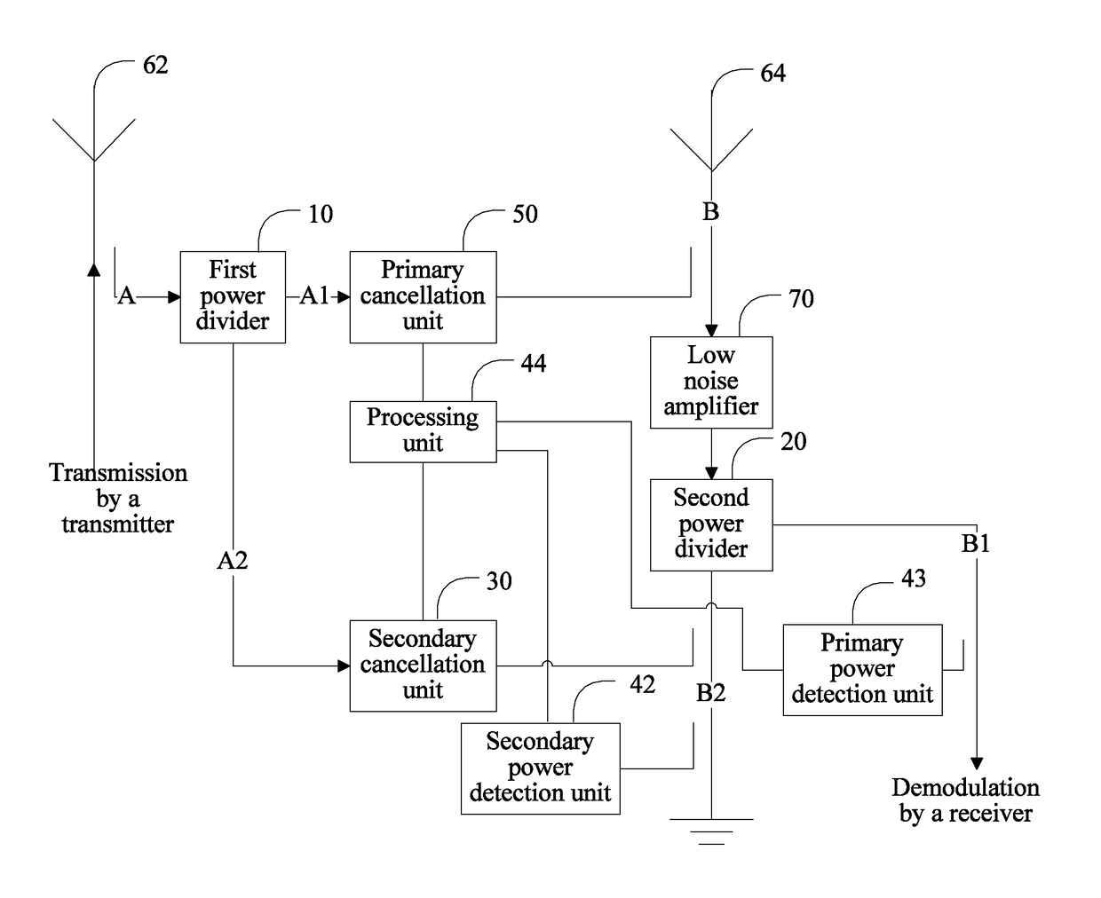
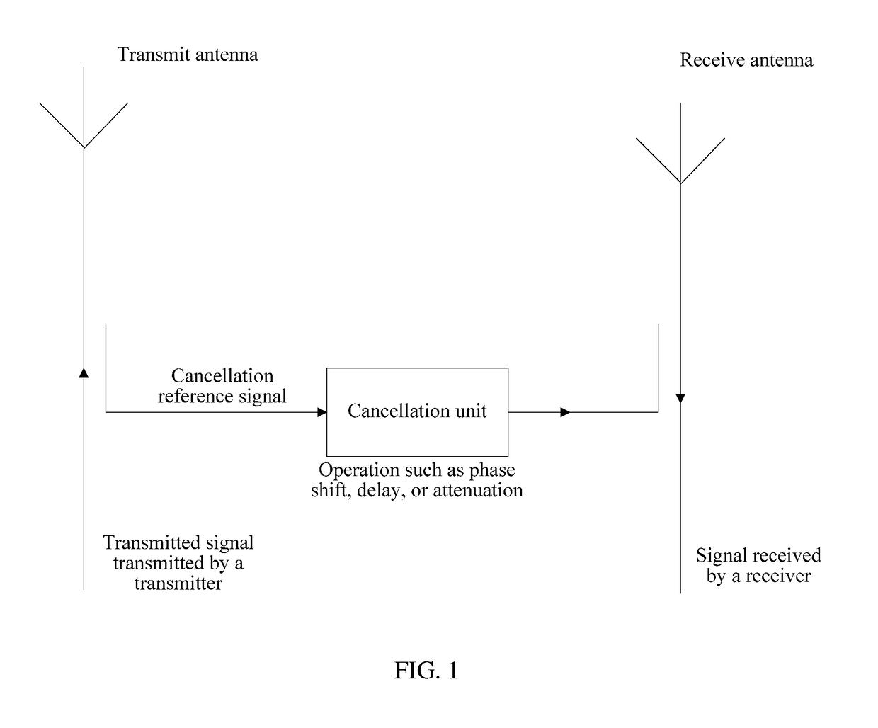
[0023]In an interference cancellation method in a conventional technology, a noise power may be temporarily increased when a phase, a delay, or an attenuation degree of a cancellation reference signal is adjusted, and consequently a communications system is unstable. To resolve the foregoing technical problem, an interference signal cancellation apparatus of a first architecture is particularly provided. As shown in FIG. 3, the interference signal cancellation apparatus ...


PUM


Abstract

An interference signal cancellation apparatus, includes a first power divider configured to divide a cancellation reference signal link corresponding to a transmit antenna into a first reference link and a second reference link. The apparatus includes a second power divider configured to divide a signal receiving link connected to a receive antenna into a first receiving link and a second receiving link, and use the first receiving link as an output link. The apparatus includes a primary cancellation unit that is located at the first reference link and that is connected to the signal receiving link by using a coupler. The apparatus includes a secondary cancellation unit that is located at the second reference link and that is connected to the second receiving link by using a coupler. The apparatus includes a control module connected to the second receiving link, the primary cancellation unit, and the secondary cancellation unit.

Description

CROSS-REFERENCE TO RELATED APPLICATIONS[0001]This application is a continuation of International Application No. PCT / CN2015 / 080441, filed on May 30, 2015, the disclosure of which is hereby incorporated by reference in its entirety.TECHNICAL FIELD[0002]The present disclosure relates to the field of communications technologies, and in particular, to an interference signal cancellation apparatus and method.BACKGROUND[0003]A key technical problem in radio and microwave communication is interference suppression and cancellation. In an existing communications system, a transmit antenna logically used for transmitting a signal and a receive antenna logically used for receiving a signal may physically be a same antenna or different antennas. However, although the transmit antenna and the receive antenna are physically different antennas, the transmit antenna and the receive antenna are generally relatively close to each other because a physical cabling layout of the communications system is...

Claims


Application Information

Patent Timeline
Patent Type & Authority Patents(United States)
IPC IPC(8): H04B1/00H04B1/7107H04B15/02H04B17/00H04B1/10
CPCH04B1/10H04B15/02H04B1/7107H04B1/525
Inventor LIU, YU
Owner HUAWEI TECH CO LTD
Why Eureka
Try Eureka