Dual-rotor electric rotating machine

a technology of electric rotating machines and rotating shafts, which is applied in the direction of rotating magnets, synchronous machines with stationary armatures, cooling/ventilation arrangements, etc., can solve the problems of reducing affecting the operation affecting the efficiency of the machine, so as to achieve the effect of minimizing size, high space factor, and ensuring high performan

Active Publication Date: 2018-07-31
DENSO CORP
View PDF21 Cites 5 Cited by
  • Summary
  • Abstract
  • Description
  • Claims
  • Application Information

AI Technical Summary

Benefits of technology

[0010]With the above configuration, it is possible to mount the at least one stator winding to the stator core only by inserting the substantially U-shaped electric conductor segments into the slots of the stator core. That is, it is unnecessary to wind the at least one stator winding around the stator core. Consequently, it is possible to prevent an insulating coat of the at least one stator winding from being damaged during the mounting of the at least one stator winding to the stator core without lowering the space factors of the at least one stator winding in the slots of the stator core. In other words, it is possible to secure high space factors of the at least one stator winding in the slots of the stator core. As a result, it is possible to secure high performance while minimizing the size of the dual-rotor electric rotating machine.

Problems solved by technology

On the other hand, with the above configuration, it may be difficult to wind a stator winding (or armature winding) around the stator core.
Moreover, during the winding process, the stator winding may interfere with the stator core, thereby damaging an insulating coat of the stator winding.
In addition, since the stator winding and the field winding are surrounded by the stator core and the rotors, it may be difficult to effectively dissipate heat generated in those windings during operation of the machine.
Consequently, it may be difficult to secure continuous high-output operation of the machine.

Method used


Image

  • Dual-rotor electric rotating machine
  • Dual-rotor electric rotating machine
  • Dual-rotor electric rotating machine

Examples


first embodiment

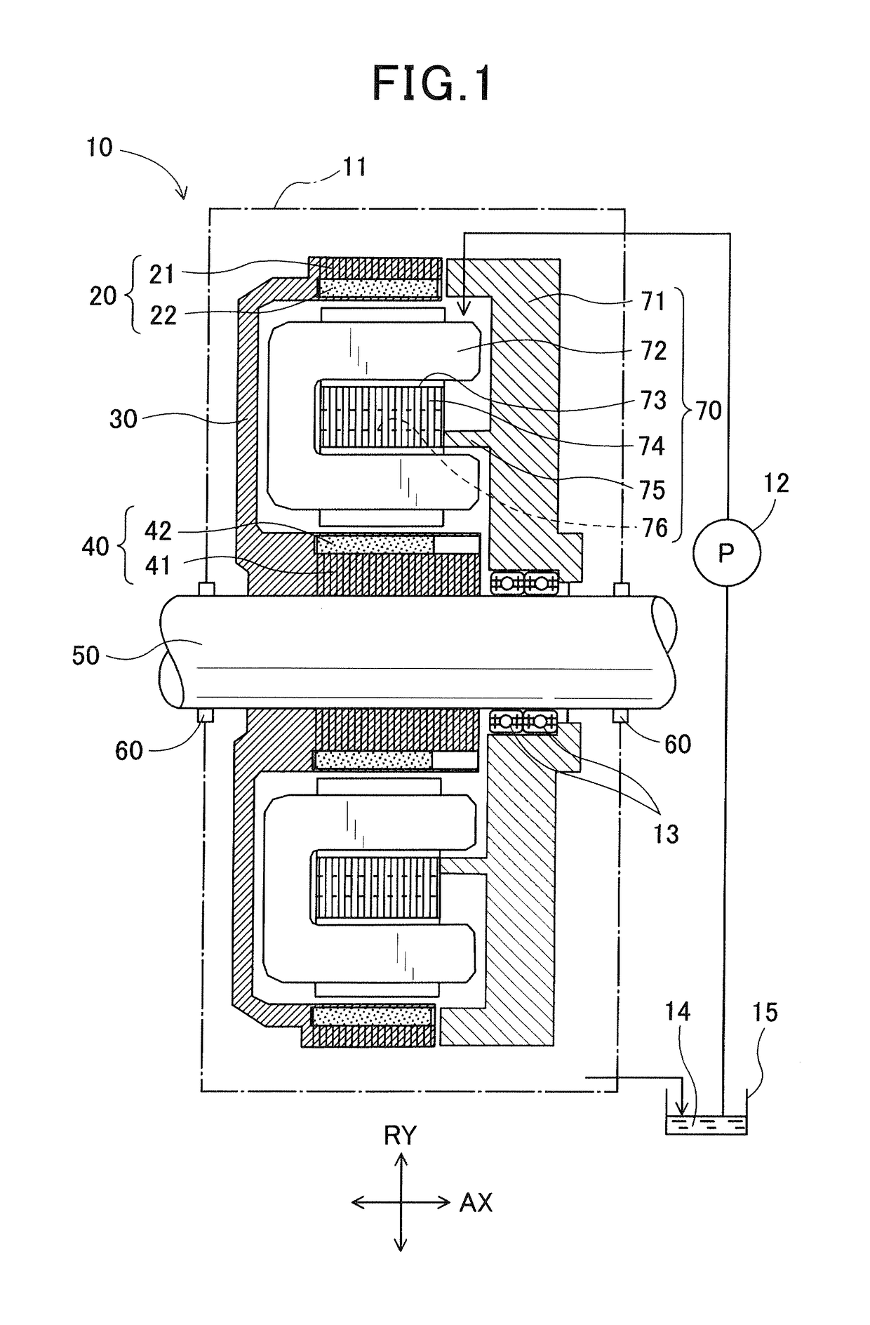
[0035]FIG. 1 shows the overall configuration of a dual-rotor electric rotating machine 10 according to a first embodiment.

[0036]In the present embodiment, the electric rotating machine 10 is configured as a motor-generator that selectively functions either as an electric motor or as an electric generator.

[0037]As shown in FIG. 1, the electric rotating machine 10 includes a housing 11, a pump 12, fluid 14, a reservoir 15, a first rotor 20, a second rotor 40, a disc portion 30, a rotating shaft 50 and a stator 70.

[0038]The housing 11, which is depicted with one-dot chain lines in FIG. 1, receives therein the first rotor 20, the second rotor 40, the disc portion 30, the rotating shaft 50 and the stator 70.

[0039]It should be appreciated that the housing 11 may be formed of any suitable material into any suitable shape provided that it can receive the aforementioned components therein.

[0040]Moreover, the fluid 14, which is drawn up by the pump 12 from the reservoir 15, flows inside the h...

second embodiment

[0101]In the previous embodiment, the number of the magnets 22 arranged on the radially inner periphery of the first rotor 20 is equal to the number of the magnets 42 arranged on the radially outer periphery of the second rotor 40. Moreover, each of the magnets 22 of the first rotor 20 is radially aligned with a corresponding one of the magnets 42 of the second rotor 40. In other words, each of the magnets 42 of the first rotor 20 is not offset from the corresponding magnet 42 of the second rotor 40 in the circumferential direction of the stator core 74 (i.e., the left-right direction in FIG. 10).

[0102]In comparison, in the present embodiment, as shown in FIG. 14, each of the magnets 22 of the first rotor 20 is offset from a corresponding one of the magnets 42 of the second rotor 40 in the circumferential direction of the stator core 74 by a predetermined angle θ. In addition, the predetermined angle θ may be greater than or equal to 25° and less than or equal to 35°.

[0103]With the ...

third embodiment

[0104]In the previous embodiments, each of the magnets 22 of the first rotor 20 overlaps a corresponding one of the magnets 42 of the second rotor 40 in a radial direction of the stator core 74 (see FIGS. 10 and 14).

[0105]In comparison, in the present embodiment, some of the magnets 22 are omitted from the first rotor 20 as indicated with two-dot chain lines in FIG. 15; though not shown in the figure, some of the magnets 42 are omitted from the second rotor 40. Consequently, none of the magnets 22 of the first rotor 20 overlap any of the magnets 42 of the second rotor 40 in a radial direction of the stator core 74. That is, in the present embodiment, the magnets 22 of the first rotor 20 are arranged alternately with the magnets 42 of the second rotor 40 in the circumferential direction of the stator core 74 (i.e., the left-right direction in FIG. 15).

[0106]As a result, in the present embodiment, each of the magnets 22 of the first rotor 20 is radially aligned with a consequent magne...


PUM


Abstract

A dual-rotor electric rotating machine includes a stator and first and second rotors that are arranged with the stator interposed therebetween. The stator includes a stator core, at least one stator winding and a stator core support. The at least one stator winding is formed of a plurality of electric conductor segments each of which is substantially U-shaped to have a base and a pair of end portions. The electric conductor segments are received in slots of the stator core so that the end portions of the electric conductor segments are located on the same side of the stator core as the stator core support and the bases of the electric conductor segments are located on the opposite side of the stator core to the stator core support. Each corresponding pair of the end portions of the electric conductor segments are electrically connected with each other.

Description

CROSS-REFERENCE TO RELATED APPLICATION[0001]This application is based on and claims priority from Japanese Patent Application No. 2014-55111, filed on Mar. 18, 2014, the content of which is hereby incorporated by reference in its entirety into this application.BACKGROUND[0002]1. Technical Field[0003]The present invention relates to a dual-rotor electric rotating machine which includes a stator and two rotors that are arranged so as to have the stator interposed therebetween.[0004]2. Description of Related Art[0005]Japanese Patent Application. Publication No. JP2003230262A discloses an electric rotating machine. This machine includes a rotor core (or field core) that is substantially U-shaped in cross section so as to have a pair of surfaces separated from and facing each other. On each of the surfaces of the rotor core, magnet magnetic poles are circumferentially arranged at equal intervals alternately with non-magnet magnetic poles. Further, a field winding is arranged at a positio...

Claims


Application Information

Patent Timeline
Patent Type & Authority Patents(United States)
IPC IPC(8): H02K9/19H02K16/02H02K15/12H02K9/10H02K21/12H02K3/12H02K3/24H02K1/20
CPCH02K9/19H02K3/12H02K9/10H02K16/02H02K21/12H02K15/125H02K3/24H02K1/20
Inventor KUSASE, SHIN
Owner DENSO CORP
Why Eureka
Try Eureka