Method for controlling electrodes for bio-impedance measurements and apparatus for bio-impedance measurements

a bioimpedance measurement and control circuit technology, applied in the field of bioimpedance measurement apparatus control circuit and control circuit of bioimpedance measurement apparatus, can solve the problems of loss of accuracy and reliability of output measurements, increase of capabilities of the entire apparatus, and complexity level of control circuit, so as to reduce the cost of manufacturing different versions of the apparatus, increase the stability of the control circuit, and reduce the cost

Inactive Publication Date: 2018-08-07
BONE VITAE
View PDF25 Cites 1 Cited by
  • Summary
  • Abstract
  • Description
  • Claims
  • Application Information

AI Technical Summary

Benefits of technology

[0027]Another advantage of the invention consists in its compatibility with less advanced measurement methods, such as a two-electrode method and a four-electrode method, allowing for a common measurement module operable with each configuration of measurement electrodes. The cost of manufacturing different versions of an apparatus is lowered, as a single apparatus can work with different sets of measurement cables corresponding to different measurement methods. When the common measurement module is intended for use with the less developed electrode sets, further cost lowering is possible by not soldering the elements unnecessary for those methods onto the common printed circuit board of the control circuit.
[0028]Another advantage of the invention consists in the increased stability of the control circuit related to the fact, that after the screening potential is established, the changes in measuring current influence the screening potential to minimal extent. In the opposite case, when the measurement potential is established initially, the secondary change in the screening potential substantially influences the magnitudes of the measuring current and the measurement potential resulting from its flow.

Problems solved by technology

When parasitic current flows through tissues which are not under investigation it can create significant problems, resulting in loss of accuracy and reliability of the output measurements.
As the number of measurement electrodes grows, the complexity level of the control circuit, and the number of pins in the connector between the control circuit and the electrodes, grows as well, but the measurement capabilities of the entire apparatus are increased.
However, the use of too low a measuring current, decreases the signal to noise ratio and lowers the sensitivity of the apparatus.
This makes implementing the measurement method difficult in practice.

Method used


Image

  • Method for controlling electrodes for bio-impedance measurements and apparatus for bio-impedance measurements
  • Method for controlling electrodes for bio-impedance measurements and apparatus for bio-impedance measurements
  • Method for controlling electrodes for bio-impedance measurements and apparatus for bio-impedance measurements

Examples


example 1

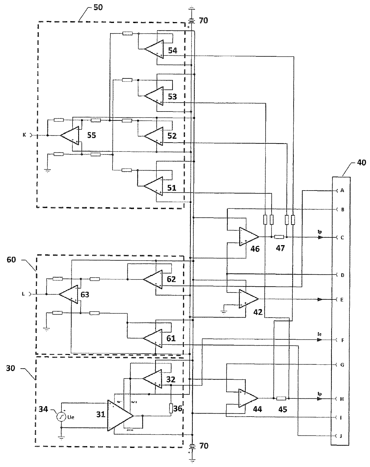
[0053]In a first example the control circuit for electrodes for bio-impedance measurements is as shown in FIG. 3 and comprises a screening current generator 30, consisting of the digital voltage generator 34 driving a current source which consists of the differential amplifier 31 and the separation amplifier 32. The screening current Ie, depends on the values of the voltage Ue and the precision resistor 36, and is output to the pin F of the measurement socket 40. The screening current Ie is received through the amplifier 42 which generates potential at the pin E of the measurement socket 40 in such a way that potential at the pin D is equal to the ground potential. The amplifiers 44 and 46 generate measuring current at the pins H and C of the measurement socket 40, respectively. A double difference amplifier 50 consisting of the operational amplifiers 51, 52, 53, 54, 55 measures potentials at the test resistors 45 and 47, and provides at the measurement output K a voltage signal pro...

example 2

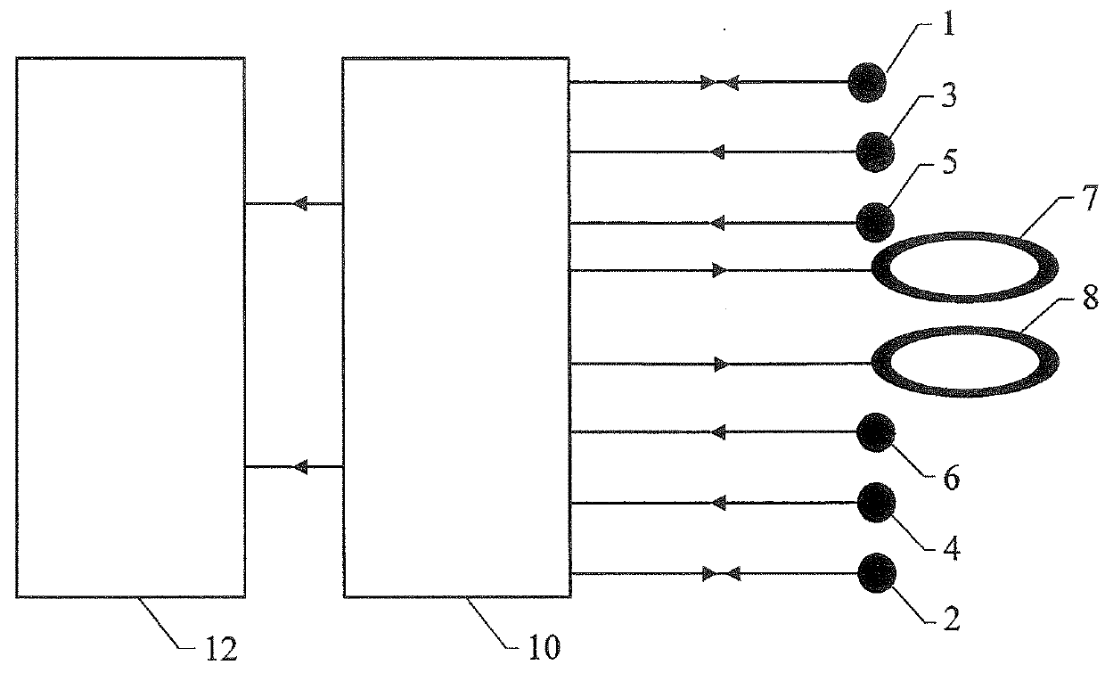
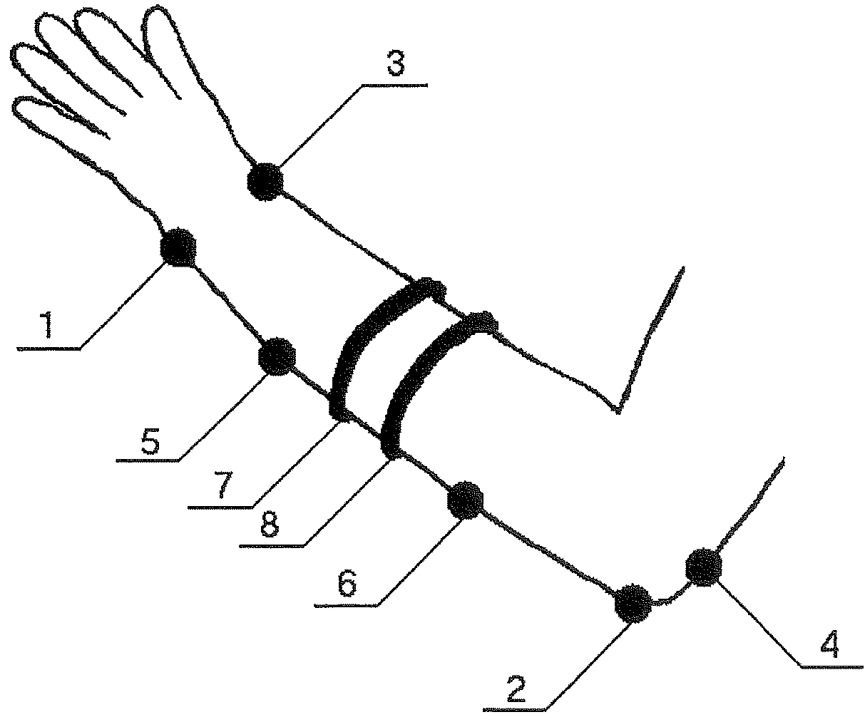
[0054]In a second example, the control circuit is the same as in Example 1 but only the measuring current injecting electrodes 1, 2, the electrodes measuring the potential produced by the measuring current flow 3, 4, and the screening current injecting electrodes 7, 8 are used. The connection of electrodes is shown in FIG. 5. The screening current injecting electrode 7 is connected to the pins D and E of the measurement socket 40. The screening current injecting electrode 8 is connected to the pins F and G. The measuring current injecting electrodes 1 and 2 are connected to the pins C and H, respectively. The electrode measuring the potential produced by the measuring current flow 3 is connected to the pins A and B. The electrode measuring the potential produced by the measuring current flow 4 is connected to the pins I and J. This way, the symmetric 6-electrode configuration of measurements with dynamic screening is realized.

example 3

[0055]In a third example, the control circuit is the same as in the Example 1 but only the measuring current injecting electrodes 1, 2, the electrodes measuring the potential produced by the measuring current flow 3, 4, and the screening current injecting electrode 8 are used. The connection of electrodes is shown in FIG. 6. The screening current injecting electrode 8 is connected to the pin F of the measurement socket 40. The measuring current injecting electrode 1 is connected to the pin C. The measuring current injecting electrode 2, which in this configuration injects also the screening current Ie, is connected to the pins D and E. The electrode measuring the potential produced by the measuring current flow 3 is connected to the pins A and B. The electrode measuring the potential produced by the measuring current flow 4 is connected to the pin J. The pins I and H are short to each other, and the pin G is short to the ground of the circuit. This way, the simplest 5-electrode conf...


PUM

PropertyMeasurementUnit
resistancesaaaaaaaaaa
supply voltagesaaaaaaaaaa

Abstract

Method for Controlling Electrodes for Bio-impedance Measurements and Apparatus for Bio-impedance Measurements There is provided a control circuit for electrodes in a bio-impedance measurement system, the bio-impedance measurement system comprising screening current injecting electrodes and measuring current injecting electrodes, the control circuit comprising: a current generator for connection to at least one screening current injecting electrode; and an measuring signal output configured to establish a measuring potential between the measuring current injecting electrodes, wherein the control circuit is configured such that the measuring potential is dependent on a measure of a potential difference resulting from the screening current. The control circuit uses the value of the potential resulting from the screening current to determine the potential difference between the measuring current injecting electrodes. In this way the flow of measuring current can be made smaller than the screening current and necessarily at a safe level.

Description

FIELD OF THE INVENTION[0001]The present invention relates to a method for controlling electrodes in a bio-impedance measurement apparatus and a control circuit for electrodes in a bio-impedance measurement apparatus. In particular, the invention relates to a method and control circuit that allows for a plurality of different bio-impedance measurement methods to be used by simply changing the configuration of the connection of the electrodes.BACKGROUND TO THE INVENTION[0002]Bio-impedance measurement techniques are known in the art. Bio-impedance measurement consists of passing a known current through tissues and measuring the resulting potential difference. Bio-impedance measurements can be used to determine a variety of properties of the tissue under investigation, for example for determining the structure of bone tissue.[0003]To obtain accurate and useful results, it is essential to measure the potentials appearing across the tissues under investigation and not the potential across...

Claims


Application Information

Patent Timeline
Patent Type & Authority Patents(United States)
IPC IPC(8): G01N27/02A61B5/053G01N33/483A61B5/00
CPCG01N33/4833A61B5/053G01N27/02A61B5/4509A61B5/6824A61B5/4504
Inventor JUST, MARCIN PAWELTYC, MICHAL HUGOLOS, PRZEMYSLAW
Owner BONE VITAE
Why Eureka
Try Eureka