Tissue fluorescence monitor with ambient light rejection

a fluorescence monitor and tissue technology, applied in the field of medical imaging systems, can solve the problems of limited ability of fluorescent markers to guide surgical procedures, limit the speed, sensitivity and applicability of methods

Active Publication Date: 2018-08-14
WISCONSIN ALUMNI RES FOUND
View PDF19 Cites 2 Cited by
  • Summary
  • Abstract
  • Description
  • Claims
  • Application Information

AI Technical Summary

Benefits of technology

[0004]The present invention provides a fluorescence imaging system that coordinates with a rapidly switched ambient lighting system, the latter turning on and off at a speed substantially imperceptible to the human eye. The apparently short periods of darkness during the switching process are exploited to perform fluorescence imaging without significant interference from the ambient light. By making fluorescence imaging compatible with bright illumination, the invention allows the fluorescence imaging equipment to be moved into a surgical suite or used in modified form for in vivo examination of tissue.
[0008]It is a feature of at least one embodiment of the invention to provide a system compatible with fluorescence imagers with highly sensitive detectors as may be needed to properly visualize faint fluorescence. The nature of LEDs and the human eye allow for the duty cycle of the illumination to be much smaller than the duty cycle of the capture cycle, allowing the majority of time to be reserved for capture with a minimal loss of capture time.
[0014]It is thus a feature of at least one embodiment of the invention to provide a system that may synchronize an arbitrary number of different light sources needed to illuminate an area and that accommodates possible timing limitations of the scanning process of the fluorescence imager.
[0016]It is thus a feature of at least one embodiment of the invention to provide a system that may work with relatively simple lighting systems, for example those that maintain a global, stable pattern of on- and off-times, for example, synchronized to a power main frequency.

Problems solved by technology

While such fluorescent markers potentially simplify the identification of tumors, the ability of fluorescent markers to guide surgical procedure is limited by the time required to transport tissue samples to a remote location suitable for fluorescence analysis.
In this scenario, ambient illumination remains active but is dimmed and light filters are typically used and this limits the speed, sensitivity and applicability of the method due to the reduced signal and added background noise.

Method used


Image

  • Tissue fluorescence monitor with ambient light rejection
  • Tissue fluorescence monitor with ambient light rejection
  • Tissue fluorescence monitor with ambient light rejection

Examples


Embodiment Construction

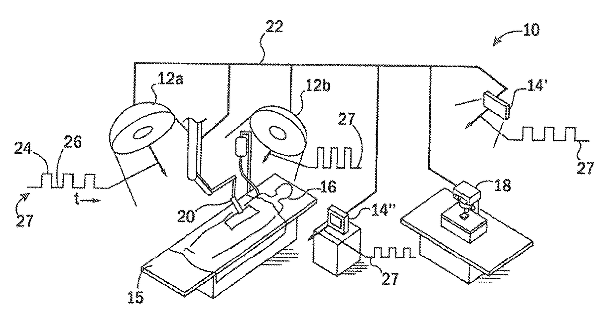
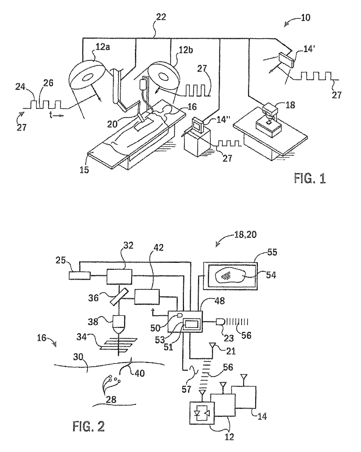
[0030]Referring now to FIG. 1, a surgical suite 10 or the like may provide for multiple area illuminators 12a and 12b, for example, positioned to illuminate an operating room table 15 holding a patient 16 for surgery. In addition, the surgical suite 10 may include multiple display lights 14 and other sources of light including, for example, display lights 14 providing for visual signals, for example an illuminated sign display light 14′ (e.g. an exit sign) or a computer monitor display light 14″ (e.g. an LCD backlight or LED array), presenting data to an attending physician.

[0031]The surgical suite 10 may further hold a desktop fluorescence microscope 18 for use contemporaneously with surgery to analyze ex vitro tissue from the patient 16 or a surgical fluorescence surgical imaging system 20, for example, suspended for direct viewing of tissue of the patient in vivo, or at the tip of an endoscope which may provide for microscopic or macroscopic imaging as will be described.

[0032]Eac...


PUM

PropertyMeasurementUnit
frequencyaaaaaaaaaa
fluorescenceaaaaaaaaaa
fluorescence imageaaaaaaaaaa

Abstract

Fluorescent markers used to identify a tissue may be imaged in a bright environment by synchronizing the imaging process with rapidly switched ambient lighting so that imaging occurs in phase with a switching off of the ambient lighting. In this way, valuable fluorescent imaging may be performed in an environment that appears to be brightly illuminated, for example in the area of a surgical suite.

Description

STATEMENT REGARDING FEDERALLY SPONSORED RESEARCH OR DEVELOPMENTCROSS REFERENCE TO RELATED APPLICATIONBACKGROUND OF THE INVENTION[0001]The present invention relates to a medical imaging system for detecting faint fluorescence signals and in particular to a fluorescence imaging system usable in brightly lit environments, for example, in a surgical suite.[0002]Fluorescent marker compounds that target cancerous tumors hold promise in allowing rapid identification of ex vitro tissue, for example, as obtained from a biopsy. The fluorescence signal developed by such marker compounds is relatively faint and normally viewed with special fluorescent microscopes that selectively illuminate the tissue with a proper exciting waveform and that include sensitive imaging systems that can isolate and detect the return fluorescence signal. Multiphoton and confocal microscope optics, for example, may be used to isolate the fluorescence signal from specific tissue while image intensifiers such as photo...

Claims


Application Information

Patent Timeline
Patent Type & Authority Patents(United States)
IPC IPC(8): A61B5/00G01N21/64A61B1/04
CPCA61B5/0071A61B5/0062G01N21/6428A61B5/0068A61B1/043G01J3/4406G01J2001/448G01J1/4228G01J2003/106G01J3/10G01J3/0262G02B21/0012G02B21/008G02B21/365A61B1/0655
Inventor MACKIE, THOMASUSELMANN, ADAMVELTEN, ANDREASPRAJAPATI, SURENDRAELICEIRI, KEVIN
Owner WISCONSIN ALUMNI RES FOUND
Why Eureka
Try Eureka