Apparatus for producing wound stators of dynamo electric machines formed from assembly of pole segments

a technology of dynamo electric machines and apparatus, which is applied in the direction of electrical apparatus, dynamo-electric machines, magnetic circuit shapes/forms/construction, etc., can solve the problems of high cost and long production time, and inability to meet the needs of the customer,

Active Publication Date: 2018-08-14
ATOP SPA
View PDF13 Cites 6 Cited by
  • Summary
  • Abstract
  • Description
  • Claims
  • Application Information

AI Technical Summary

Benefits of technology

[0009]It is an object of the present invention to provide an apparatus and a method for assembling pole segments with a high degree of automation.
[0010]It is also an object of the present invention to provide an apparatus and a method capable of accomplishing transfer of an assembly of pole segments maintaining the positioning accuracy of the pole segments.
[0012]It is also another object of the present invention to provide an apparatus and a method for positioning an assembly of pole segments accurately for being worked on.

Problems solved by technology

The existing production lines of stators formed from pole segments are scarcely automatic.
The few stages that are automatic adopt general purpose robots, which have high costs and long production time.
In this situation there is a high risk of disjoining, or incorrect positioning of the pole segments during the successive work stages, which contemplate for example: transferring, termination of the coil leads, fusing of the leads to the terminals, quality inspection, definite joining of the pole segments together.

Method used


Image

  • Apparatus for producing wound stators of dynamo electric machines formed from assembly of pole segments
  • Apparatus for producing wound stators of dynamo electric machines formed from assembly of pole segments
  • Apparatus for producing wound stators of dynamo electric machines formed from assembly of pole segments

Examples


Embodiment Construction

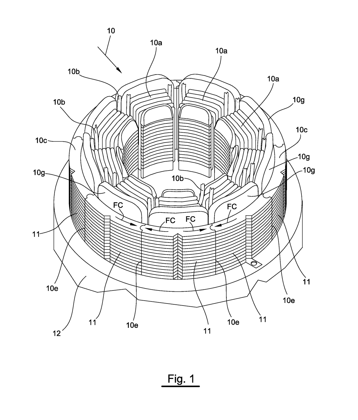
[0033]FIG. 1 shows a stator core 10 in a processing condition formed from an assembly of pole segments 11, like those described for example in EP 1,098,425. The pole segments 11 have been wound with coils 10a by means of flyer devices, or other dispensing devices. Leads 10b are extensions of the conductor wire used to wind the coils and need to be routed on predetermined paths and connected to terminals (not shown in FIG. 1), which are normally present on the insulation members 10g of the ends 10c and 10d of the pole segments 11.

[0034]As an alternative, the terminals can be present on a support member for the leads 10b placed on an end of the pole segments. An example of a support member for the leads 10b of this type is shown and more fully described in the following.

[0035]Continuous lines 10e visible in FIG. 1 represent the lateral sides of the pole segments 11. In particular, a pole segment 11 is delimited by the two axial ends 10c and 10d, and two lateral sides 10e. In the figur...


PUM

PropertyMeasurementUnit
movementaaaaaaaaaa
rotationaaaaaaaaaa
electricaaaaaaaaaa

Abstract

An apparatus for manufacturing stators of dynamoelectric machines, the stators being formed as an assembly of pole segments; the apparatus comprising a seat where the assembly of pole segments are seated. An engagement assembly engages first ends of the pole segments for translation of the pole segments from the seat to a transfer device. A first holding assembly comprises a first plurality of holding members for clamping the pole segments to hold the pole segments as an assembly of pole segments. The first holding assembly being arranged on the transfer device moveable to transfer the assembly of pole segments from a first position to a second position. A containing assembly is located at the second position and provided with a second plurality of holding members for holding the assembly of pole segments. The second plurality of holding members are positioned on the containing assembly to surround the assembly of pole segments that are located at the containing assembly.

Description

FIELD OF THE INVENTION[0001]The present invention relates to the production of stators formed from segments of single poles in the following referred to as pole segments.[0002]In particular, the solutions foreseen by the present invention relate to the assembly of pole segments for forming a wound stator.BACKGROUND OF THE INVENTION[0003]As known, each pole segment can be wound singularly with one or more electric conductors (in the following also referred to as wire).[0004]The sequence of operations by which the pole segments are produced normally provides winding the pole segments singularly, assembly of the pole segments to form the stator, connecting of the leads of the pole segments to terminals, fusing of leads of the pole segments to the terminals and definite joining of the pole segments by using external binding.[0005]An advantage of a stator formed from the pole segments consists in the increase of the quantity of electric conductor that can be present in the finished stato...

Claims


Application Information

Patent Timeline
Patent Type & Authority Patents(United States)
IPC IPC(8): H02K15/02H02K1/14
CPCH02K15/022H02K1/148Y10T29/53161Y10T29/53143Y10T29/49011
Inventor PONZIO, MASSIMOCORBINELLI, RUBINONICCOLINI, STEFANO
Owner ATOP SPA
Why Eureka
Try Eureka