
Pre-cast decorative retaining wall system

a decorative retaining wall and precast technology, applied in the field of concrete retaining wall construction, can solve the problems of liquid portion of concrete dripping into the sand, none of these previous efforts, however, provides the benefits attendant with the precast decorative retaining wall system, and achieves the effects of reducing construction costs, reducing construction costs, and reducing construction costs

Active Publication Date: 2018-08-21
ECO CONCRETE SOLUTIONS
View PDF24 Cites 5 Cited by
  • Summary
  • Abstract
  • Description
  • Claims
  • Application Information

AI Technical Summary

Benefits of technology

The Pre-cast Decorative Retaining Wall has several technical benefits. It can be manufactured at a factory and transported to a building site, or pre-fabricated or manufactured on the final installation or building site. It can incorporate transparent materials that can be back lit by various lighting means. It is safer to use because it does not require scaffolding, making it safer to build. It is faster to build because it is independent of footings and can be done before the footings are complete. The unique buttress support system has been designed that reduces the moment arm about which the wall rotates, allowing for safer and longer wall heights. The attachment of rebar to the wall can be done by various methods, such as bending rebar parallel to the wall surface or using commercially available anchoring systems. Overall, the Pre-cast Decorative Retaining Wall has improved safety and efficiency.

Problems solved by technology

Thus the stone and sand are less readily displaced by concrete poured over them during vibration, causing a liquid portion of the concrete to diffuse into the sand.
None of these previous efforts, however, provides the benefits attendant with the Pre-cast Decorative Retaining Wall System.

Method used


Image

  • Pre-cast decorative retaining wall system
  • Pre-cast decorative retaining wall system
  • Pre-cast decorative retaining wall system

Examples


Embodiment Construction

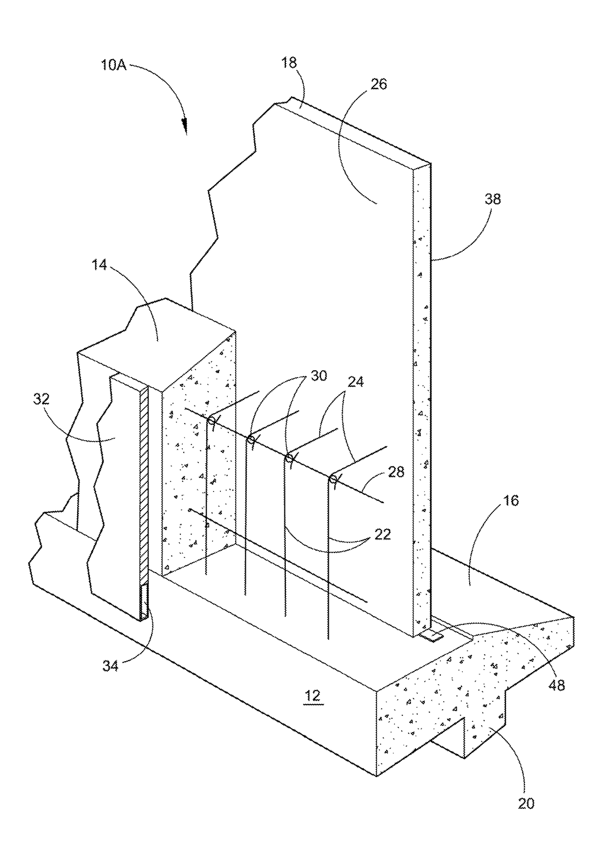
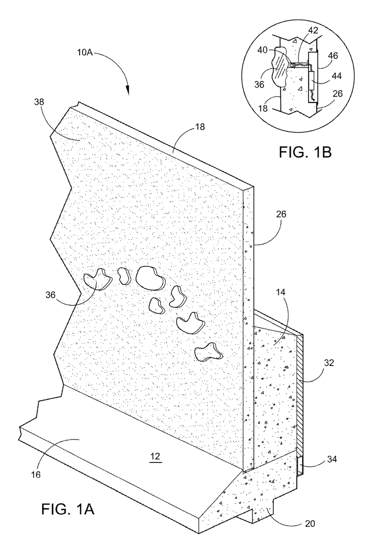
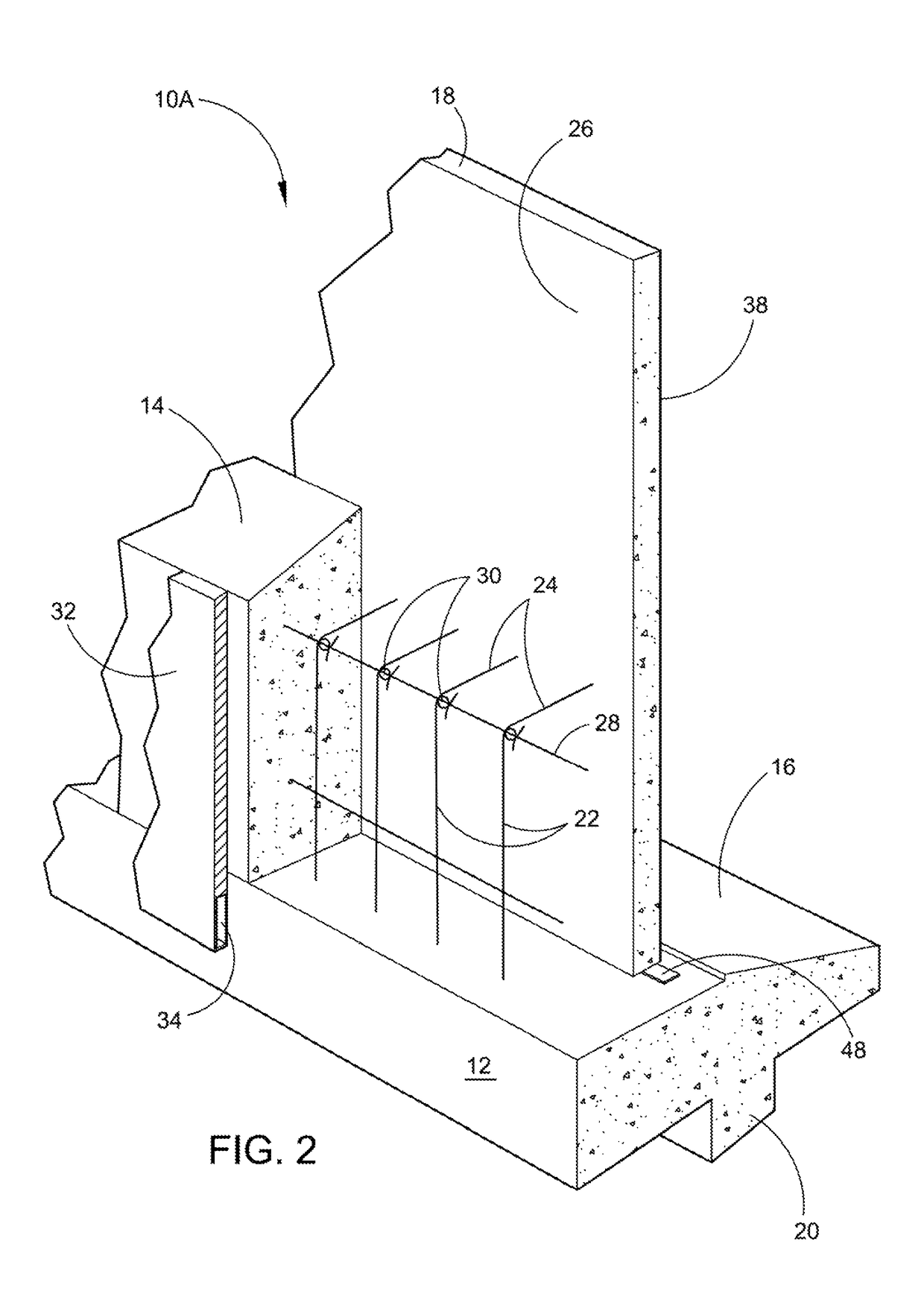
[0068]Referring now to the drawings, wherein similar parts of the Pre-cast Decorative Retaining Wall 10A, 10B and 10C are identified by like reference numerals, there is seen in FIG. 1A a perspective section view of the Precast Decorative Retaining Wall 10A on a footing 12 with the buttress support 14. The footing 12 will have a toe section 16 in front of the wall 18 and a footing, key 20 on the lower surface. Conventional waterproofing coatings will be applied to the wall back side 26 of the wall 18 and a water transmitting material 32 with a drainage cavity 34 at the bottom on the back side of the buttress support 14. Alternatively, a waterproofing, agent may be added to the concrete mix with only a drainage system required. A tesserae 36 wall design is illustrated on the front wall surface 38 of the wall 18. It should be understood that when constructed, the pre-cast wall may be readily decorated on either the front wall surface 38 or the wall back side 26 as desired.

[0069]FIG. 1...


PUM


Abstract

The present invention is directed to a Pre-cast Decorative Retaining Wall consisting of concrete walls constructed on a horizontal surface normally at a manufacturing facility, on rolling platforms, or preferably built on the construction site where after curing to 3000 psi the pre-fabricated walls can be shipped to and installed at a building site. In the flat state the panels can have a wide variety of decorative elements readily applied to both the upper and lower downside reflection surface. A unique feature is the buttress system that is added to the back of the wall system when elevated retention is required. By pouring the buttress portion on top of the footing pier or caisson, and tying into the pre-decorated wall with reinforcement, an eco-friendly, design optional retaining wall system is accomplished which can be rapidly and safely installed.

Description

FIELD OF THE INVENTION[0001]The present invention provides a process for constructing concrete retaining walls. More particularly, the present invention provides a process for constructing concrete retaining walls at a remote location using pre-fabricated wall panels with a unique variety of design and decoration capabilities the customer can create, and then have transported to the building site, or be pre-fabricated on the building site, to be installed as a retaining wall using a specially designed footing and buttress support system if required, or as a monument wall or fence.BACKGROUND OF THE INVENTION[0002]Pre-cast tilt-up, cast on site or off site, (also known as Pre-cast tilt-slab or tilt-wall) concrete construction is not new and has been in use since the turn of the century. Since the mid-1940s it has developed into the preferred method of construction for many types of buildings and structures in the U.S. Pre-cast concrete construction has many advantages that are well kn...

Claims


Application Information

Patent Timeline
Patent Type & Authority Patents(United States)
IPC IPC(8): E02D29/02
CPCE02D29/0283E02D29/0275E02D29/0266E02D29/02
Inventor BAUMGARTNER, RUSSEL W.TAYLOR, RICHARD K.BAUMGARTNER, LIZZY N.
Owner ECO CONCRETE SOLUTIONS
Learn More