Self-correcting scope

a self-correcting and scope technology, applied in the field of scopes, can solve the problems of lack of visual acuity or spatial understanding to effectively mentally, lack of skill in firearm use, and inability to accurately shoot, etc., to achieve simple design and construction, easy installation, and easy setup and maintenance.

Inactive Publication Date: 2018-08-21
REIMER PAUL
View PDF28 Cites 3 Cited by
  • Summary
  • Abstract
  • Description
  • Claims
  • Application Information

AI Technical Summary

Benefits of technology

[0007]The self-correcting scope of the present invention addresses the aforementioned needs in the art by providing a scope that is mounted onto a projectile discharge device such as a firearm, a paintball gun, a BB gun, a bow of a bow and arrow system, etc., and which automatically provides correction for a user for the upcoming shot based on the data captured from the previous shot. The self-correcting scope, having a physical mounting profile that mimics a traditional optical scope, mounts to the projectile discharge device in typical fashion and is used for aim purposes in typical scope fashion, although the user looks at a display screen as opposed to looking through an ocular eyepiece. This makes the self-correcting scope relatively easy to install and easy to setup and maintain. The self-correcting scope is of relatively simple design and construction, being produced using standard manufacturing techniques, so as to make the device readily affordable to a large segment of potential consumers of this type of device. In field use, the self-correcting scope is easy to utilize and very quick so that once shot correction is needed, the function is performed very fast in order to allow a corrected subsequent shot to be discharged in order to hit the intended target before the target disappears or before the target gets its own shot off in the direction of the user.

Problems solved by technology

Unfortunately, many firearms users, as well as users of other projectile discharge devices, such as paintball guns, BB guns, bow and arrow systems, etc., are not as skilled in firearm usage and tend to be less accurate in their shooting.
However, many shooters lack either the visual acuity or the spatial understanding to effectively mentally calculate their shooting error and are not able to effectively account for the error.
Additionally, many shooters, possibly faced with a strong cross wind, simply feel uncomfortable aiming the scope off target in order to compensate for the wind and will bring the scope back on target, only to miss the target from the wind effects.
Similar problems arise for distance shots when accounting for gravitational effects.
For shooters that can quickly and effectively calculate their shot error and compensate their sighting through the scope with the next shot, the few seconds such calculation and compensation require, many be problematic.
For a soldier on the battlefield, the time delay for error compensation may prove fatal.

Method used


Image

  • Self-correcting scope
  • Self-correcting scope
  • Self-correcting scope

Examples


Embodiment Construction

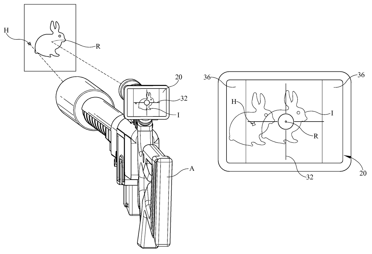
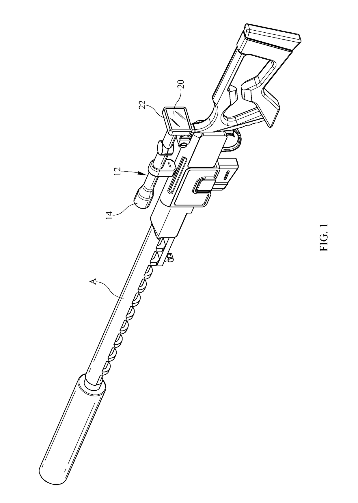
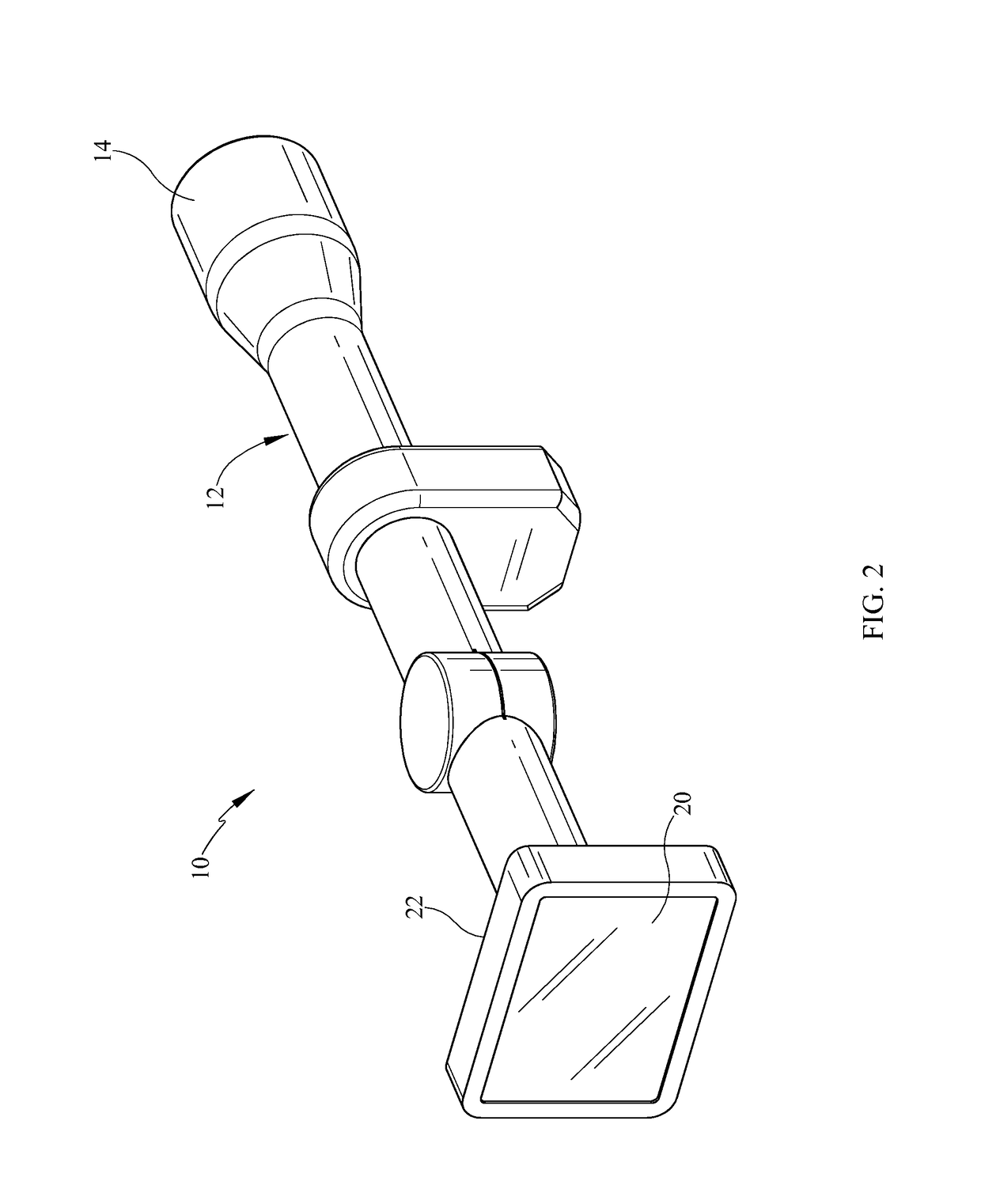
[0017]Referring now to the drawings, it is seen that the self-correcting scope of the present invention, generally denoted by reference numeral 10, is comprised of a scope body 12 that has a first end 14 and a second end 16 such that an optical lens 18 is disposed within the first end 14 of the scope while an image display device 20 is located on the second end 16 of the device. The digital display device 20, which is a typical digital display screen, and which may be a touch screen display of appropriate design, and may be held in a housing 22 that is pivotally attached to the remainder of the scope body 12 in order to allow the housing 22 and thus the display device 20 to be able to pivot with respect to the remainder of the scope body 12.

[0018]A first digital image sensor 24 is located within the scope body 12 as is a second digital image sensor 26, each in signal processing communication with a computer 28 also located within the scope body 12. The computer 28 has storage capaci...


PUM


Abstract

A self-correcting scope compares the original aim point of a projectile discharge device with the actual impact point and self-corrects the scope to account for the offset between these two points. The scope uses a typical optical lens which converts the incoming image to a digital image which is displayed by the invention on a digital display device which functions as the “eyepiece” of the scope. The invention also compresses the image either to the left or to the right or both of the field of interest in order to allow a shooter to be able to detect an intrusion into the field on interest from a point farther than can be achieved in a non-compressed image.

Description

BACKGROUND OF THE INVENTION1. Field of the Invention[0001]The present invention relates to a scope, such as a scope used on a projectile discharge device, such as a firearm, paintball gun, bow and arrow system, etc., wherein the scope provides digital imaging output to the user such that after the projectile discharge device is discharged, the scope calculates the offset between the aim point of the scope and the actual impact point of the fired round and recalibrates the scope based on the offset.2. Background of the Prior Art[0002]Some firearm users are able to initially sight a firearm in, often at an indoor range where wind is not a factor, at a given distance, and thereafter use the sighted in firearm under almost any condition. Such users are sufficiently adept at using firearms so that they can calculate the offsets presented by wind, distance differential (from the distance used at sight in), load being shot, humidity, etc., and use the firearm with great accuracy. Such fire...

Claims


Application Information

Patent Timeline
Patent Type & Authority Patents(United States)
IPC IPC(8): F41G1/38F41G1/473
CPCF41G1/38F41G1/473
Inventor REIMER, PAUL
Owner REIMER PAUL
Why Eureka
Try Eureka