Control system for unmanned aerial vehicle utilizing parallel processing architecture

a control system and unmanned aerial vehicle technology, applied in vehicle position/course/altitude control, process and machine control, instruments, etc., can solve the problems of complex control of flight of multi-rotor uav, high processing cost, and large real estate requirements

Active Publication Date: 2018-08-21
HOVERFLY TECH INC
View PDF2 Cites 8 Cited by
  • Summary
  • Abstract
  • Description
  • Claims
  • Application Information

AI Technical Summary

Problems solved by technology

As a result, UAVs 10 lend themselves to applications where other aircraft are not viable.
Helicopters also possess this ability to move at six degrees of freedom, but in application provide only moderately stable platforms for applications such as still photography, filming, surveillance, and remote sensing.
Although relatively simplistic in structure, control of flight of a multi-rotor UAV 10 is both subtle and complex.
This large amount of computer processing requires an expensive sophisticated computer capable of processing multiple dynamic inputs in real time to control a plurality of motors in unison to maintain flights stable enough to support an activity such as video surveillance.
As a result, computer 22 is expensive and may require significant real estate upon platform 12.
However, serial operation results in some instability even with the use of the high priced computers.

Method used


Image

  • Control system for unmanned aerial vehicle utilizing parallel processing architecture
  • Control system for unmanned aerial vehicle utilizing parallel processing architecture
  • Control system for unmanned aerial vehicle utilizing parallel processing architecture

Examples


Embodiment Construction

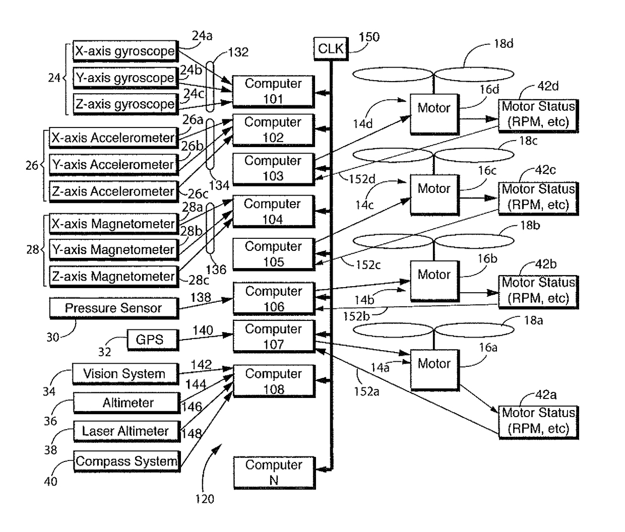
[0015]Reference is made to FIG. 3 in which a control system, generally indicated as 120, for controlling the flight of UAV 10 in accordance with the invention is provided. Like numerals are utilized to indicate like structure to facilitate description.

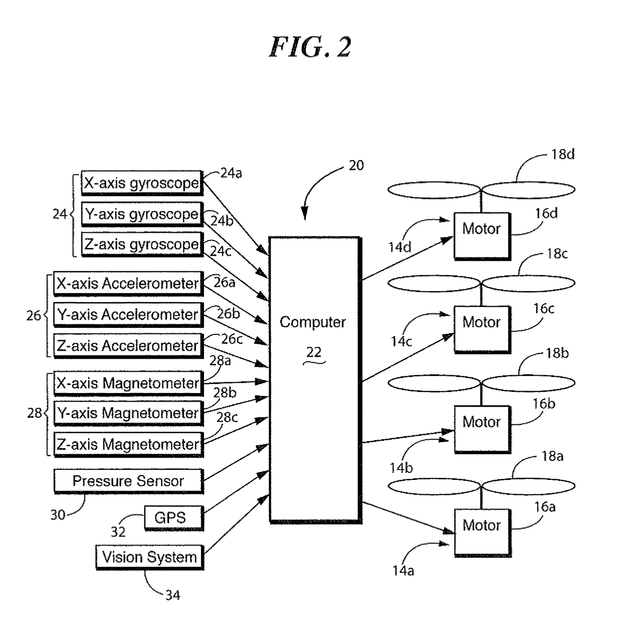
[0016]It should be noted, that for operation of the inventive system 120, no modification need be made to the sensor or to the rotors. Accordingly, motion sensors includes gyroscope array 24 including a gyroscope 24a for detecting motion relative to the X-axis, a gyroscope 24b for detecting motion relative to the Y-axis and a gyroscope 24c for detecting motion relative to the Z-axis. An accelerometer array 26 has components for detecting acceleration of the X-axis 26a and a sensor 26b for measuring acceleration relative to the Y-axis and a sensor 26c for measuring acceleration in the Z-axis. A magnetometer array 28 is also included and includes X-axis magnetometer 28a, a Y-axis magnetometer 28b and Z-axis magnetometer 28c. The sensors ...


PUM


Abstract

A UAV has two rotors. First and second sensors sense a first and second type of input respectively. The second type of input is different than the first type, the first sensor providing a first sensor output and the second sensor providing a second sensor output. The first sensor output is input to a first computer and the second sensor output is input to a second computer. The first and second computer communicate in parallel to process the first and second sensor outputs to create a control signal having a predetermined number of variables therein, each variable having an exclusive position within the signal. The first computer outputs a first variable and the second computer outputs a second variable, each output being assigned an exclusive position within the control signal. At least one of the first and second computers outputting the control signal to the rotors.

Description

CROSS REFERENCE TO RELATED APPLICATION(S)[0001]This application is a non-provisional U.S. Patent Application, which claims priority to Provisional Patent Application No. 61 / 551,718, filed Oct. 26, 2011, in its entirety and is hereby incorporated by reference.BACKGROUND OF THE INVENTION[0002]This invention is directed to the flight control of an unmanned aerial vehicle, and in particular, a system for parallel processing inputs from sensors to control a multi-rotor unmanned aerial vehicle.[0003]Reference is now made to FIG. 1 in which an unmanned aerial vehicle (UAV) generally indicated as 10, as constructed in accordance with the prior art, is shown. UAV 10 is a free floating aerial platform 12. A plurality of rotors 14a, 14b, 14c and 14d in this example are attached to platform 12. Each rotor 14a-14d includes respective motor 16a-16d which is mechanically coupled to a respective propeller 18a-18d. Rotors 14a-14d are operated under the control of the control system 20 as known in th...

Claims


Application Information

Patent Timeline
Patent Type & Authority Patents(United States)
IPC IPC(8): G05D1/00G05D1/08
CPCG05D1/0858G05D1/0088
Inventor SAPP, II, GEORGE RICHARDDUCHARME, ALFRED D.BURROUGHS, DANIELDUCHARME, STACEY L.
Owner HOVERFLY TECH INC
Why Eureka
Try Eureka