Supercharge Your Innovation With Domain-Expert AI Agents!

Cylinder head cooling apparatus of engine

a cooling apparatus and cylinder head technology, applied in the direction of machines/engines, fuel air intakes, combustion air/fuel air treatment, etc., can solve the problems of low cooling efficiency around suppress excessive cooling of the auxiliary combustion chamber wall, and enhance the heat efficiency of the engine and the starting performance of the engine.

Active Publication Date: 2018-08-28
KUBOTA CORP
View PDF17 Cites 0 Cited by
  • Summary
  • Abstract
  • Description
  • Claims
  • Application Information

AI Technical Summary

Benefits of technology

[0006]An object of the present invention is to provide a cylinder head cooling apparatus of an engine capable of enhancing cooling efficiency around the auxiliary combustion chamber wall.
[0012]The engine cooling water flowing upstream of the auxiliary combustion chamber wall is guided by the upstream cooling water guide wall, and smoothly diverts toward both sides of the auxiliary combustion chamber wall, so that it is possible to enhance the cooling efficiency around the auxiliary combustion chamber wall.
[0013]Engine cooling water flowing upstream of the auxiliary combustion chamber wall collides against the upstream cooling water guide wall, and the auxiliary combustion chamber wall does not take a direct hit of the engine cooling water. Thus, excessive cooling of the auxiliary combustion chamber wall is suppressed, and it is possible to enhance the heat efficiency of the engine and the starting performance of the engine during a cold period.

Problems solved by technology

In the conventional cylinder head cooling apparatus of an engine, engine cooling water does not easily divert toward both sides of the auxiliary combustion chamber wall smoothly, and cooling efficiency around the auxiliary combustion chamber wall is low.

Method used


Image

  • Cylinder head cooling apparatus of engine
  • Cylinder head cooling apparatus of engine
  • Cylinder head cooling apparatus of engine

Examples


Embodiment Construction

[0022]FIGS. 1 to 8 are views for describing a cooling apparatus of a cylinder head of an engine according to an embodiment of the present invention. In this embodiment, the cooling apparatus of the cylinder head of a water-cooling vertical type two-cylinder diesel engine will be described.

[0023]An outline of the cylinder head of the engine is as follows.

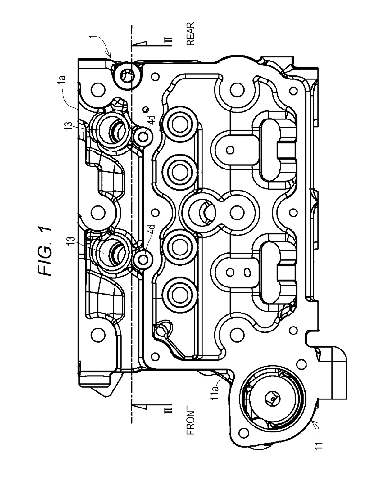
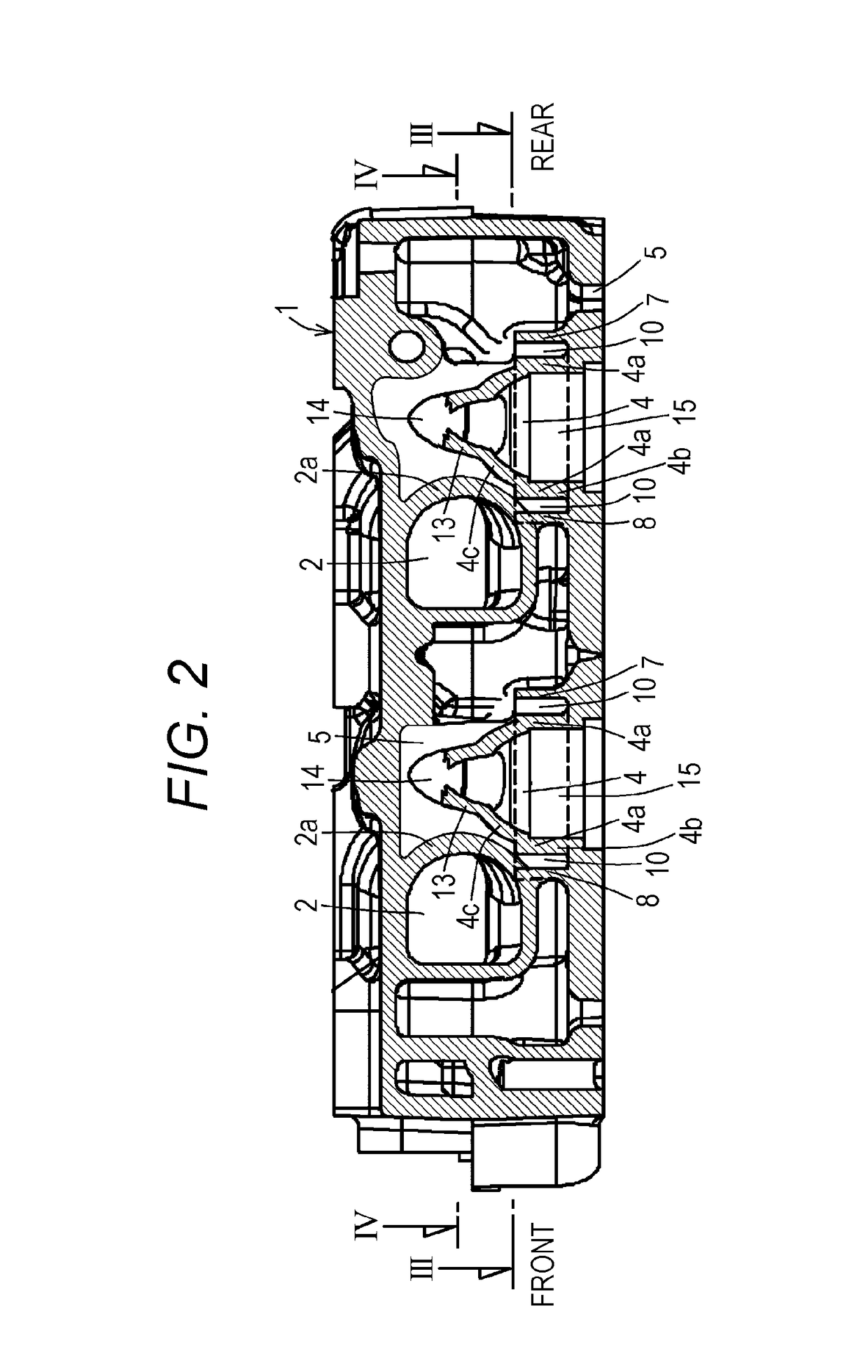
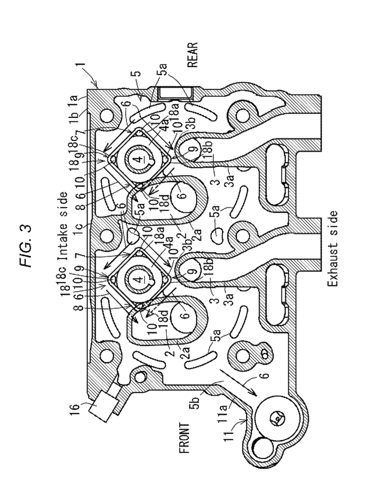
[0024]As shown in FIG. 6, an intake manifold (12) is mounted on one (1a) of lateral walls of a cylinder head (1), and an exhaust manifold (not shown) is mounted on the other lateral wall (1d). As shown in FIGS. 3 and 4, an extending direction of a crankshaft (not shown) is defined as a longitudinal direction, a pair of front and rear intake ports (2), (2) and a pair of front and rear auxiliary combustion chambers (4), (4) are placed on a suction side in the cylinder head (1), and a pair of front and rear exhaust ports (3), (3) are placed on an discharge side in the cylinder head (1). A cooling water jacket (5) is provided in the cyli...


PUM


Abstract

There is provided a cylinder head cooling apparatus of an engine capable of enhancing cooling efficiency around an auxiliary combustion chamber wall. The cylinder head cooling apparatus of an engine including a cylinder head having therein an intake port, an exhaust port, an auxiliary combustion chamber, and a cooling water jacket, in which an intake port wall, an exhaust port wall, and an auxiliary combustion chamber wall are placed in the cooling water jacket, the cooling water jacket includes a cooling water inlet and a cooling water outlet, engine cooling water flowed from the cooling water inlet into the cooling water jacket flows out from the cooling water outlet through the cooling water jacket, wherein a cooling water guide wall is provided upstream of the auxiliary combustion chamber wall in a cooling water passing path of the cooling water jacket, and the upstream cooling water guide wall is formed into a shape whose width gradually widens toward a downstream side.

Description

BACKGROUND OF THE INVENTION[0001](1) Field of the Invention[0002]The present invention relates to a cylinder head cooling apparatus of an engine.[0003](2) Description of Related Art[0004]Conventionally, as a cylinder head cooling apparatus of an engine, there is an apparatus in which engine cooling water passing through a cooling water jacket is caused to flow along a cylindrical auxiliary combustion chamber wall.[0005]In the conventional cylinder head cooling apparatus of an engine, engine cooling water does not easily divert toward both sides of the auxiliary combustion chamber wall smoothly, and cooling efficiency around the auxiliary combustion chamber wall is low.SUMMARY OF THE INVENTION[0006]An object of the present invention is to provide a cylinder head cooling apparatus of an engine capable of enhancing cooling efficiency around the auxiliary combustion chamber wall.[0007]A matter to define the present invention is as follows.[0008]A cylinder head cooling apparatus of an en...

Claims


Application Information

Patent Timeline
Patent Type & Authority Patents(United States)
IPC IPC(8): F01P3/02F02M35/10F02F1/42F02F1/14F01P11/04F02M35/104F02F1/40
CPCF01P3/02F01P11/04F02F1/14F02F1/40F02M35/104F02M35/10091F02F1/4285F01P2003/024F01P2003/021
Inventor NAGAI, KENTAROKUWASAKI, HIROSHINAKANO, TADASHIHAMASAKI, TAKAHITOTANAKA, YOSHINORIMORI, MASAYA
Owner KUBOTA CORP
Features
  • R&D
  • Intellectual Property
  • Life Sciences
  • Materials
  • Tech Scout
  • Unparalleled Data Quality
  • Higher Quality Content
  • 60% Fewer Hallucinations
Learn More