Joining method

a jointing method and joint technology, applied in the direction of lamination apparatus, layered products, chemistry apparatus and processes, etc., can solve the problems of insufficient joint strength of the members, burr generation at the joint portion, etc., and achieve the effect of increasing joint strength

Active Publication Date: 2018-09-04
TOYOTA JIDOSHA KK
View PDF12 Cites 1 Cited by
  • Summary
  • Abstract
  • Description
  • Claims
  • Application Information

AI Technical Summary

Benefits of technology

[0010]The invention thus provides a joining method capable of effectively increasing the joint strength between resin members, when joining together resin members, at least one of which is made of fiber-reinforced resin in which reinforcing fiber material is mixed into the resin.
[0013]According to this aspect, the joint forming portion that is formed by the first resin of the first member and the second resin of the second member that has softened or melted in a region adjacent to the abutting surfaces of the first member and the second member, and fiber material included in the softened or melted first resin of the first member, is stirred in a direction inclined with respect to the abutting surfaces, more specifically, a direction orthogonal to the abutting surfaces, and is hardened. Therefore, the fiber material of the first member included in the joint forming portion is able to be oriented in a direction inclined with respect to the abutting surfaces of the first member and the second member, more specifically, in a direction orthogonal to those abutting surfaces, and hardened. As a result, the joint strength between the first member and the second member is able to be dramatically increased.
[0017]According to this aspect, the fibers of the first member included in the joint forming portion are able to be easily and reliably oriented in the direction orthogonal to the abutting surfaces of the first member and the second member by moving the stirring member that has been inserted into the joint forming portion in the direction orthogonal to the abutting surfaces and stirring the joint forming portion in the direction orthogonal to the abutting surfaces.
[0019]According to this aspect, the first resin of the first member and the second resin of the second member are softened or melted from the facing surface of the first member or the facing surface of the second member by the stirring member that has been placed in contact with the facing surface of the first member that faces the abutting surface or the facing surface of the second member that faces the abutting surface, and the stirring member is inserted into the joint forming portion. As a result, the first resin of the first member and the second resin of the second member can be softened or melted using the stirring member that stirs the joint forming portion, and the stirring member can be relatively easily inserted into the joint forming portion.
[0021]According to this aspect, the first resin of the first member and the second resin of the second member are softened or melted and the stirring member that rotates around the rotational axis that is parallel to the direction orthogonal to the abutting surfaces is inserted into the joint forming portion, while moving the stirring member into the first member and the second member from the facing surface of the first member or the facing surface of the second member. As a result, the size of the joint forming portion is able to be made relatively large near the tip end portion of the stirring member, due to the heat generated at the tip end portion of the stirring member from the friction between the stirring member and the first member or the second member, so when the joint forming portion hardens, the joint strength between the first member and the second member is able to be further increased due to the anchor effect thereof.

Problems solved by technology

However, with all of these methods, the joining surfaces are pressed together with a predetermined pressure while the area near the joining surfaces is melted, so burr is generated at the joint portion, which is problematic.
Therefore, although it is desirable to orient the fibers in the direction orthogonal to the joining surface when joining these kinds of fiber-reinforced resin members together, if the members are pressed on in the direction orthogonal to the joining surface when they are joined together as described above, the fibers near the joining surface will be oriented so that they become parallel to the joining surface, which is problematic.
Therefore, the direction of orientation of the fibers inside the first thermoplastic resin member and the second thermoplastic resin member is unable to be changed, so the problem in which the joint strength of the members is unable to be sufficiently increased may remain.

Method used


Image

  • Joining method
  • Joining method
  • Joining method

Examples


Embodiment Construction

[0030]Hereinafter, example embodiments of the joining method of the invention will be described with reference to the accompanying drawings.

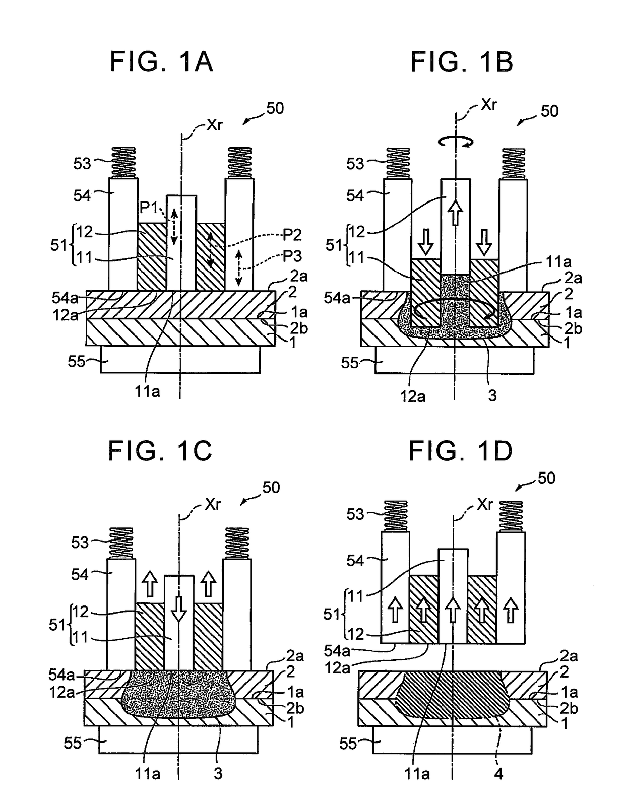
[0031]FIG. 1 is a longitudinal view illustrating one example embodiment of the joining method of the invention, with FIG. 1A being a view of an arranging process, FIG. 1B being a view of a push-in process, FIG. 1C being a view of a pullout process, and FIG. 1D being a view of a removal process.

[0032]

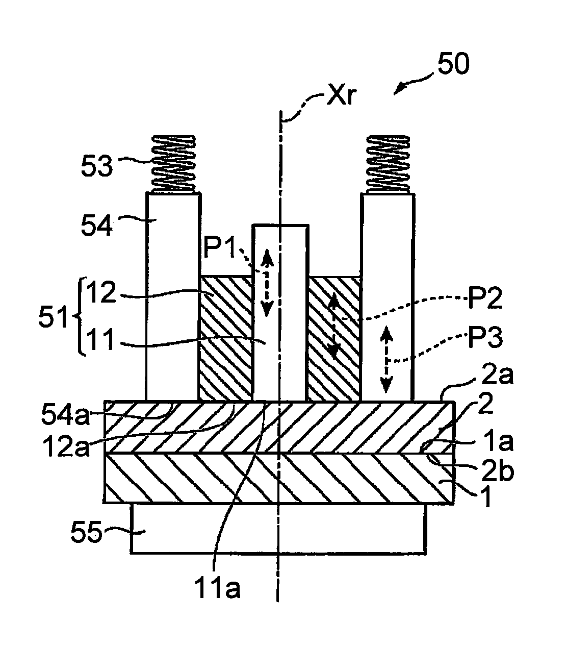
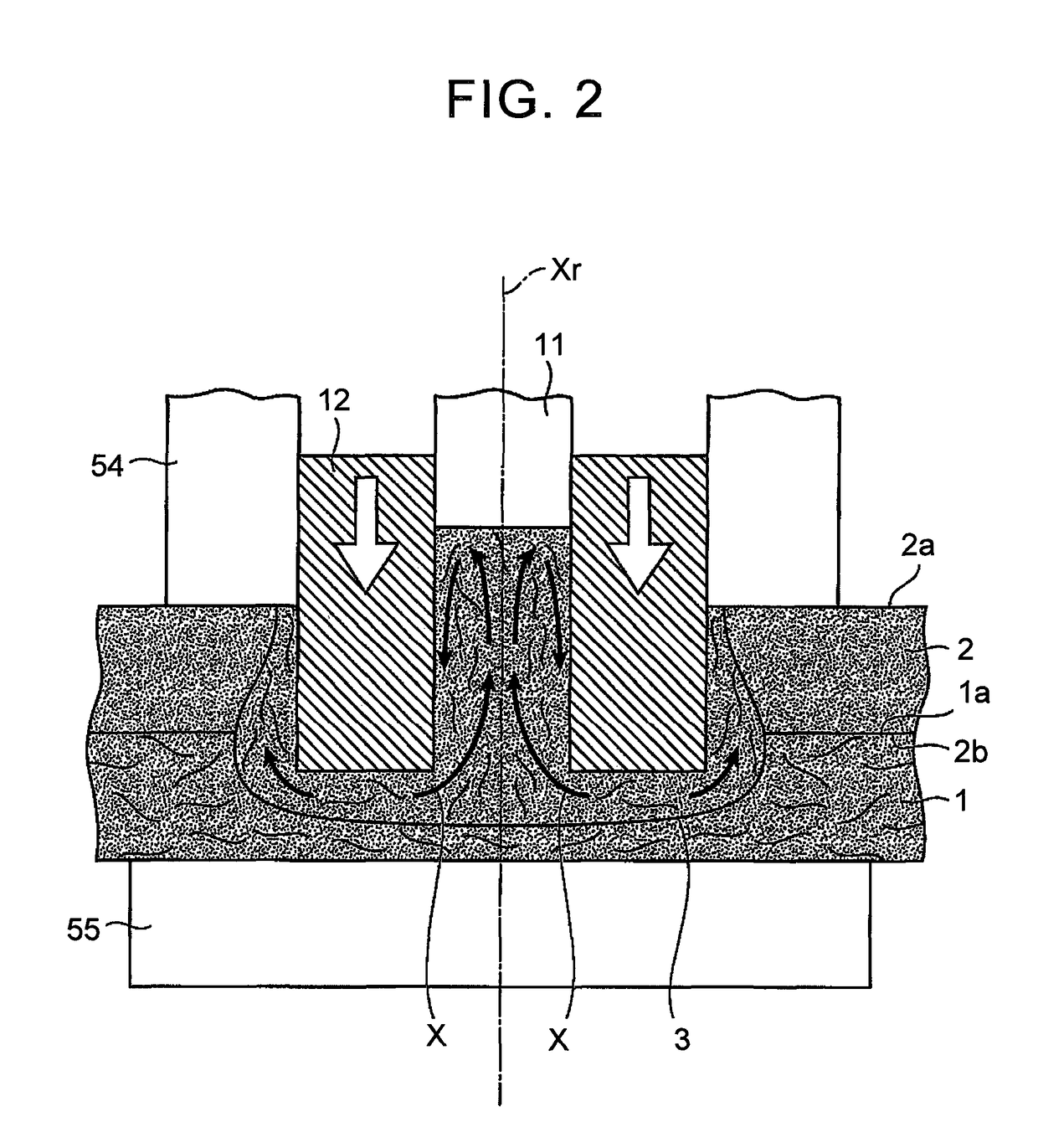
[0033]The joining method according to this example embodiment of the invention is carried out using a double action type friction stir welding apparatus as a representative example of the friction stir welding apparatus. Therefore, first the representative example of the double action type Friction Stir Welding (FSW) apparatus used with the joining method according to this example embodiment will be outlined with reference to FIG. 1A.

[0034]As shown in FIG. 1A, the FSW apparatus 50 used with the joining method according to this example embodiment main...


PUM

PropertyMeasurementUnit
frictionaaaaaaaaaa
pressureaaaaaaaaaa
stressaaaaaaaaaa

Abstract

A joining method for joining together a first member in which fiber material is mixed into a first resin, and a second member that includes at least a second resin, includes abutting the first member and the second member together, and softening or melting the first resin of the first member and the second resin of the second member that are adjacent to abutting surfaces of the first member and the second member; and stirring a joint forming portion formed by the softened or melted first resin of the first member and the softened or melted second resin of the second member, and the fiber material included in the softened or melted first resin of the first member, in a direction inclined with respect to the abutting surfaces, and hardening the joint forming portion.

Description

BACKGROUND OF THE INVENTION[0001]1. Field of the Invention[0002]The invention relates to a joining method, more particularly, a joining method for joining together fiber-reinforced resin members in which reinforcing fiber material is mixed into a matrix resin, for example.[0003]2. Description of Related Art[0004]Methods that use vibration, ultrasonic waves, friction between resin members, and heat plates, for example, are known as methods for joining fiber-reinforced resin members in which reinforcing fiber material such as glass fiber or carbon fiber is included in resin (matrix resin) or a resin member made of thermoplastic resin.[0005]However, with all of these methods, the joining surfaces are pressed together with a predetermined pressure while the area near the joining surfaces is melted, so burr is generated at the joint portion, which is problematic. Also, the fiber-reinforced resin material is strong against stress in a direction parallel to the direction of orientation of ...

Claims


Application Information

Patent Timeline
Patent Type & Authority Patents(United States)
IPC IPC(8): B32B37/00B29C65/08B29C65/06B29C65/00
CPCB29C65/0681B29C65/08B29C66/721B29C66/341B29C66/324B29C65/7841B29C66/1122B29C66/41B29C66/71B29C66/7212B29C66/7392B29C66/73921B29C66/7394B29C66/73941B29C66/81463B29C66/8161B29C66/8322B29K2063/00B29K2023/12B29K2023/06B29K2025/06B29K2055/02B29K2027/06B29K2033/12B29K2077/00B29K2067/00B29K2049/00B29K2069/00B29K2067/003B29K2067/006B29K2309/08B29K2307/04B29K2309/02B29K2305/02B29K2305/10B29K2305/12B29K2277/00B29K2267/00B29K2023/083B29K2025/08B29K2027/16B29K2031/04B29K2059/00B29K2071/00B29K2071/12B29K2075/00B29K2079/085B29K2081/04B29K2081/06
Inventor UENO, YASUHIROKIYONO, TAKAAKINAKAMURA, HIDEO
Owner TOYOTA JIDOSHA KK
Why Eureka
Try Eureka