Turbine valve actuator

a technology of turbine valve actuator and actuator, which is applied in the direction of fluid-pressure actuator, gas turbine plant, jet propulsion plant, etc., can solve the problems of high cost of development, production, storage, and distribution, and achieve the effect of conserving energy and particularly energy-saving operation of the supply devi

Inactive Publication Date: 2018-09-04
HYDAC SYST
View PDF20 Cites 1 Cited by
  • Summary
  • Abstract
  • Description
  • Claims
  • Application Information

AI Technical Summary

Benefits of technology

[0014]Particularly advantageously, the supply device for the first medium space, in an actuating drive, comprises a pressure-controlled axial piston pump having a swivel angle adjustment. Alternatively, in a switching drive, the supply device comprises a gear pump having a constant delivery volume. The supply device cooperates with the positioning device. If the supply device comprises an axial piston pump, then a proportional valve is provided in the positioning device. If the supply device comprises a gear pump, then the positioning device has a control valve. To conserve energy, the gear pump

Problems solved by technology

A subsequent adaptation of the turbine valve actuator to another steam valve is not possible.
The end result is a

Method used


Image

  • Turbine valve actuator
  • Turbine valve actuator
  • Turbine valve actuator

Examples


Embodiment Construction

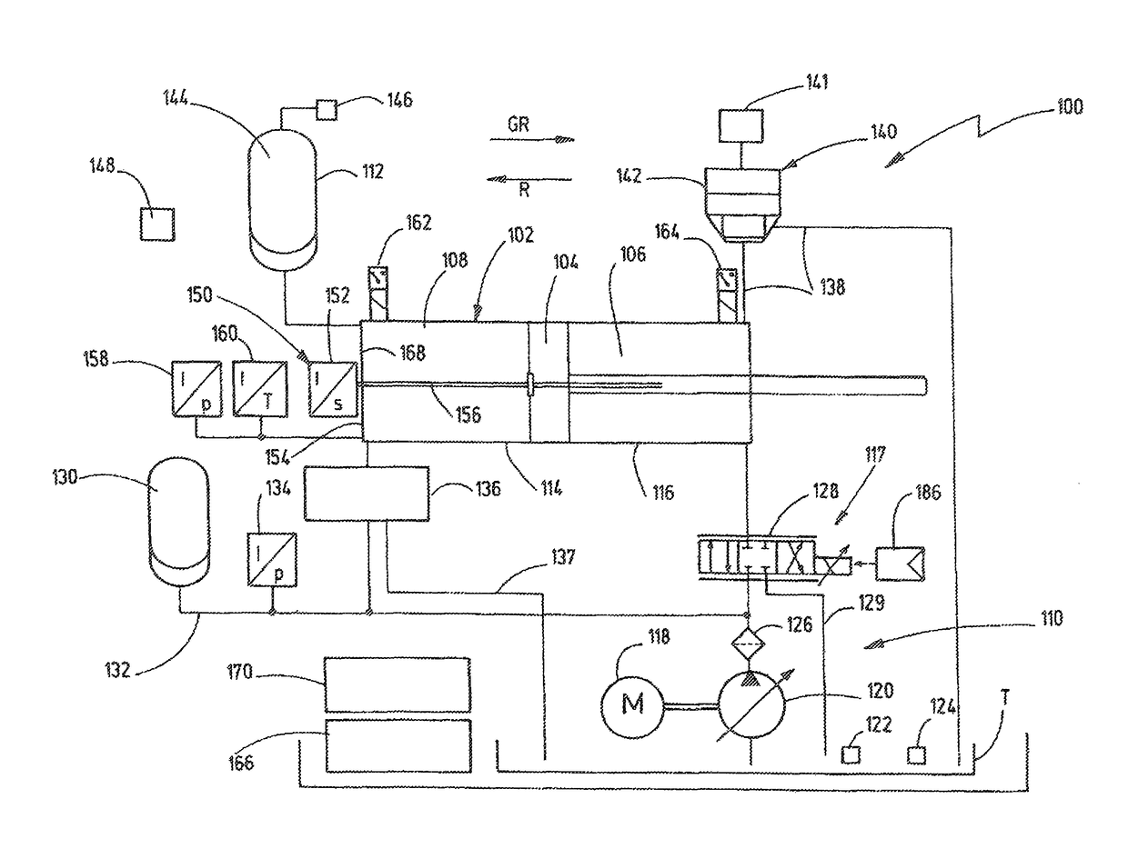
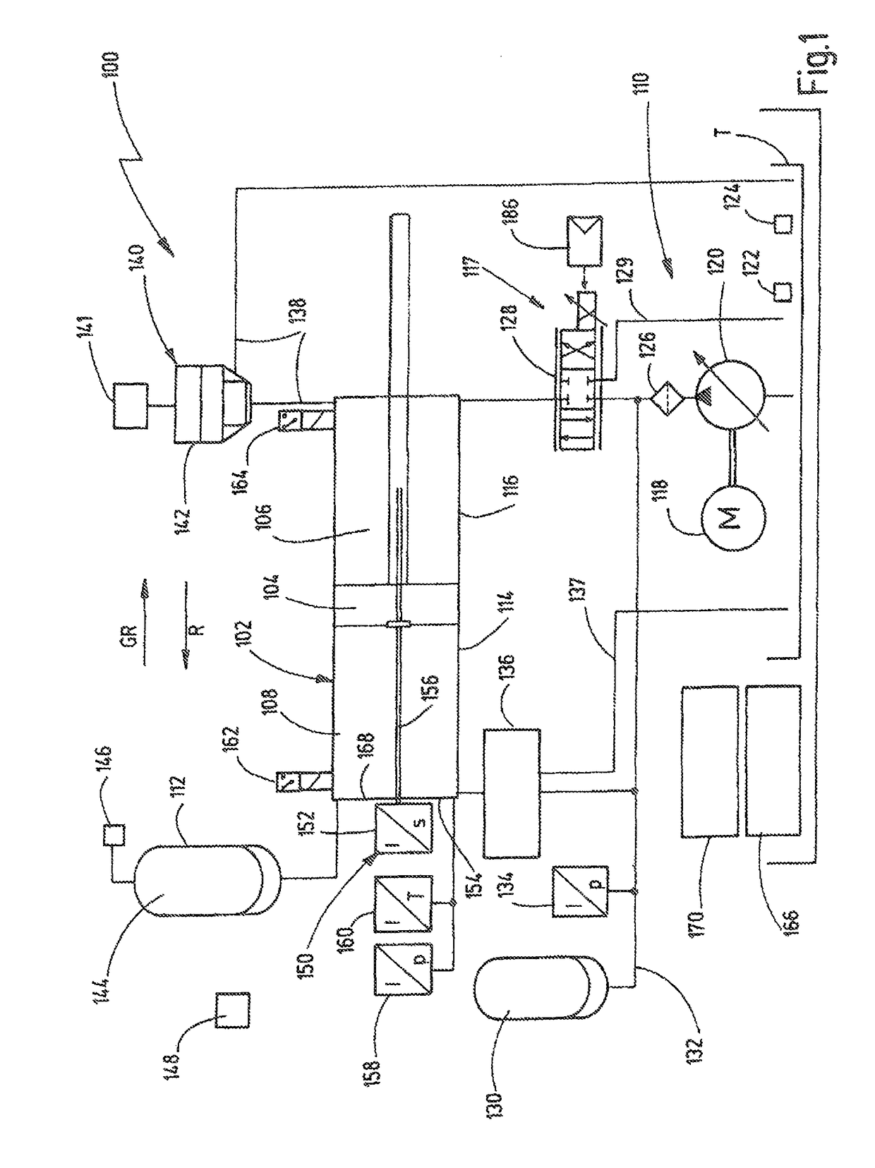
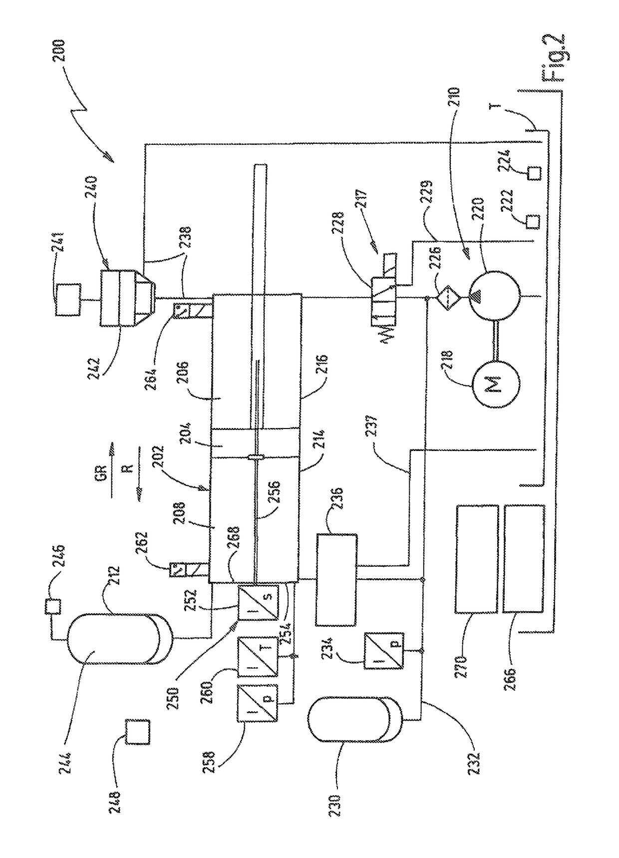
[0026]FIGS. 1 to 3 illustrate three exemplary embodiments of turbine valve actuators 100, 200, 300 according to the invention, for driving at least one valve unit (not shown) of a medium-operated consumer unit, such as a steam or gas turbine. The turbine has an actuating part drive 102, 202, 302, which comprises a movable actuating part 104, 204, 304, a first medium space 106, 206, 306, and a second medium space 108, 208, 308. A pressure build-up in the first medium space 106, 206, 306 attempts to cause or causes movement of the actuating part 104, 204, 304 in a first direction R. A pressure build-up in the second medium space 108, 208, 308 attempts to cause or causes movement of the actuating part 104, 204, 304 in an opposing second direction GR. The first medium space 106, 206, 306 can be supplied with a fluid in predeterminable amounts by a supply device 110, 210, 310. The second medium space 108, 208, 308 is acted upon by an energy accumulator 112, 212, 312. The energy accumulat...


PUM


Abstract

A turbine valve actuator (100) controls a valve unit of a media-operated consumer unit, such as a steam or gas turbine, and has an actuating part drive (102) with a movable actuating part (104), a first media space (106) and a second media space (108). A pressure build up in the first media space (106) attempts to cause a movement of the actuating part (104) in a first direction (R). A pressure build-up in the second media space (108) attempts to cause a movement of the actuating part (104) in an opposing second direction (GR). The first media space (106) can be supplied with a fluid in predeterminable amounts by a supply (110). The second media space (108) is acted upon by a hydraulic accumulator (112) provided with a preload pressure and permanently connected to the second media space (108).

Description

FIELD OF THE INVENTION[0001]The invention relates to a turbine valve actuator for controlling at least one valve unit of a medium-operated consumer unit, such as a steam or gas turbine. The valve actuator an actuating part drive that comprises a movable actuating part, at least one first medium space, and at least one second medium space. A pressure build-up in the first medium space attempts to cause a movement of the actuating part in a first direction. A pressure build-up in the second medium space attempts to cause a movement of the actuating part in an opposing second direction. The first medium space can be supplied with a fluid in predeterminable amounts by a supply device. The second medium space is acted upon by an energy accumulator.BACKGROUND OF THE INVENTION[0002]Turbine valve actuators are known in the prior art, e.g., from patent document DE 10 2004 042 891 B3. That turbine valve actuator includes a hydraulic working cylinder. A piston rod unit is permanently spring-lo...

Claims


Application Information

Patent Timeline
IPC IPC(8): F15B11/08F15B1/08F15B15/14F02C9/16
CPCF15B11/08F15B1/08F15B15/1476F02C9/16F15B2211/8752F15B2201/31F15B2201/4155F15B2211/20538F15B2211/20546F15B2211/212F15B2211/31511F15B2211/329F15B2211/513F15B2211/5158F15B2211/526F15B2211/6306F15B2211/6336F15B2211/6343F15B2211/7052F15B2211/7656F15B2211/7716F15B2211/8633
Inventor SCHLEMMER, KRISTOFPIECHNICK, MARTINBRITZ, WOLFGANG
Owner HYDAC SYST
Why Eureka
Try Eureka