Control system design assist device, control system design assist program, control system design assist method, operation change amount calculation device and control device

a technology of control system and assist device, which is applied in the direction of electric controllers, instruments, controllers with particular characteristics, etc., can solve problems such as instable control system, and achieve the effect of improving control performance and low cos

Active Publication Date: 2018-09-04
FUJI ELECTRIC CO LTD
View PDF8 Cites 0 Cited by
  • Summary
  • Abstract
  • Description
  • Claims
  • Application Information

AI Technical Summary

Benefits of technology

[0018]On the other hand, the model prediction control in Non-Patent Documents 2 and 3 yields high control performance, but requires high computing performance in order to carry out progressive on-line optimization, and therefore involves large implantation costs compared to general PID control. Furthermore, even if on-line calculation is carried out using control rules obtained in advance by off-line calculation, as in Non-Patent Document 4, the control rules become huge in size when the state space of the control object becomes large, and therefore high computing performance is required also.
[0021]According to the present disclosure, it is possible to design a control system having improved control performance taking account of time response, such as inverse response, at low cost.

Problems solved by technology

However, in PID control, the operation amount varies to a greater extent, the larger the difference between the target value and the control amount, and therefore if an inverse response occurs in which the control amount changes in the opposite direction to the target value, with change in the operation amount, then undershooting may occur, and the control system may become instable.

Method used


Image

  • Control system design assist device, control system design assist program, control system design assist method, operation change amount calculation device and control device
  • Control system design assist device, control system design assist program, control system design assist method, operation change amount calculation device and control device
  • Control system design assist device, control system design assist program, control system design assist method, operation change amount calculation device and control device

Examples


Embodiment Construction

[0049]The following features, at the least, are clear from the description of the disclosure and the accompanying drawings.

(Configuration of Control System Design Assist Device)

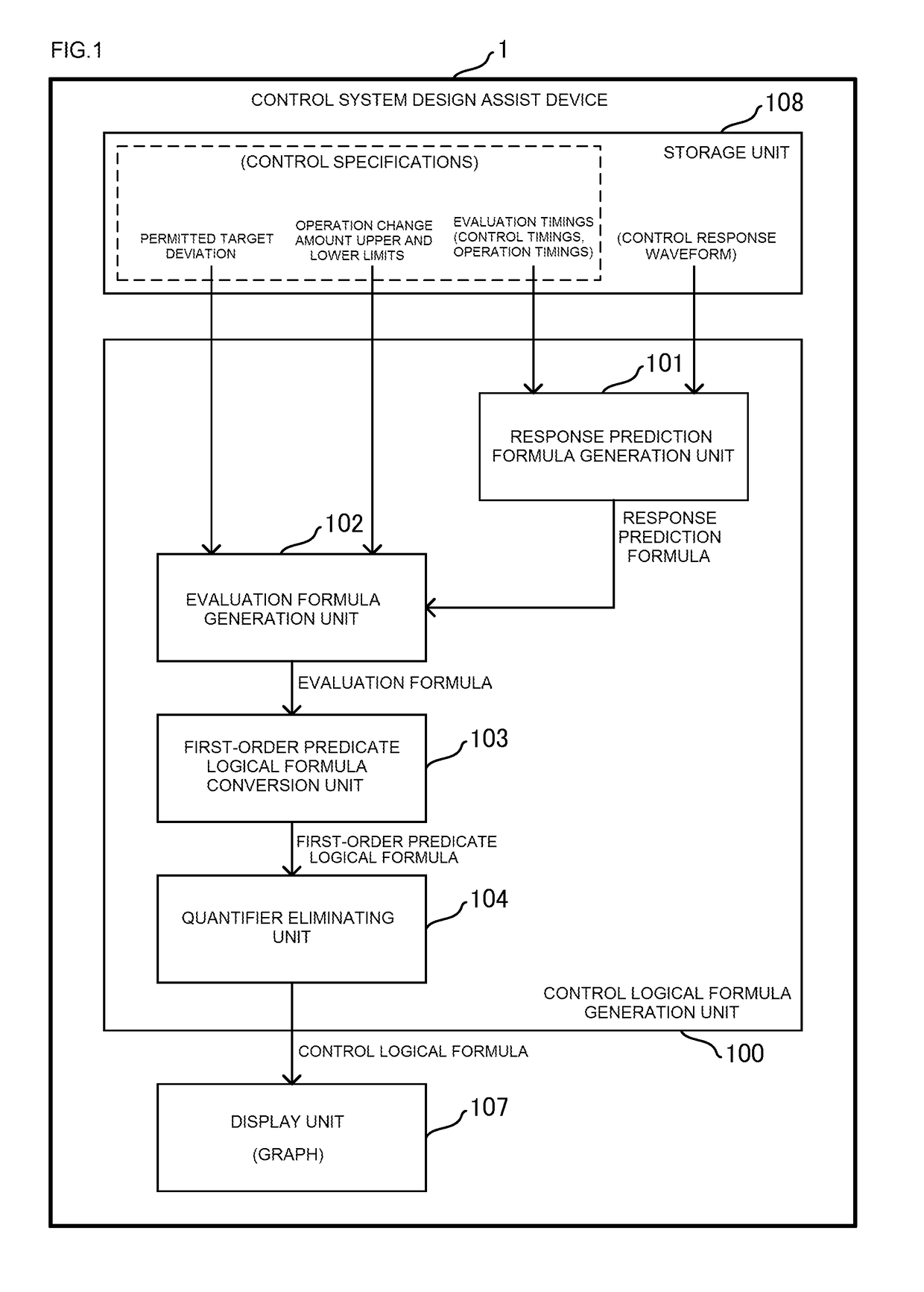
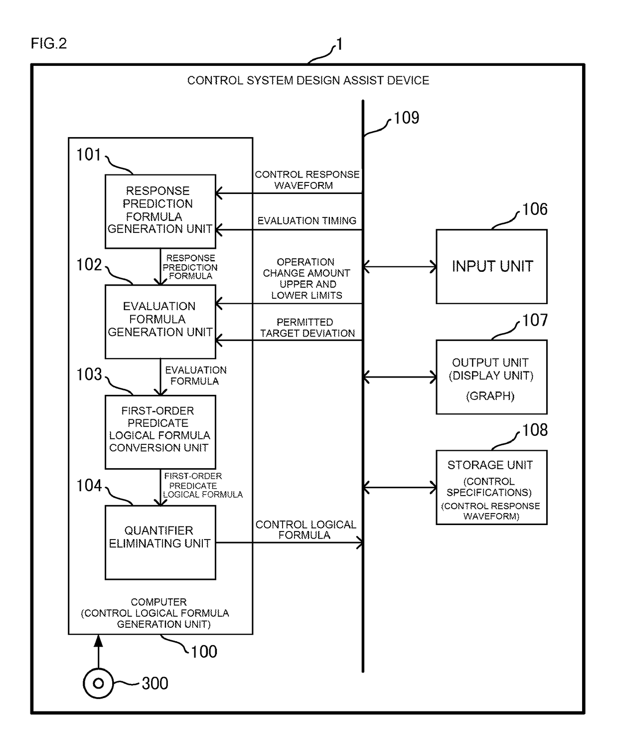
[0050]Below, the configuration of a control system design assist device according to one embodiment of the present disclosure is described with reference to FIG. 1 and FIG. 2.

[0051]Here, firstly, FIG. 3 illustrates the relationship between a control amount, a control amount variation value, an operation amount and an operation change amount which are used in the following description.

[0052]The control amount Y is the output of the control object, which is measured by a meter, such as a sensor, and is an amount that is controlled so as to become a set target value r (dash line). On the other hand, the control amount variation value y is the value of the variation of the control amount Y from an initial value Y0 at time t=0, and is given by y(t)=Y(t)−Y0. The control timing ti (i=1, . . . , n) is a timing at whi...


PUM


Abstract

A control system design assist device which assists design of a control system that controls a control object such that the control object outputs a control amount according to a target value. The design assist device generates a response prediction formula predicting a variation value of the control amount at each control timing included in the sequence of control timings by using an amount of change of the operation amount at each operation timing included in the sequence of operation timings; generates evaluation formulas; and converts a logical product formula into a first first-order predicate logical formula. The design assist device generates a control logical formula indicating a relationship between the current value of the target deviation and the change amount of the operation amount.

Description

CROSS-REFERENCE TO RELATED APPLICATIONS[0001]This application is a continuation application, filed under 35 U.S.C. § 111(a), of International Application PCT / JP2014 / 077221 filed on Oct. 10, 2014, and claims foreign priority to, Japanese Patent Application No. 2013-218092 filed on Oct. 21, 2013, the contents of both of which are incorporated herein by reference.BACKGROUND[0002]1. Field[0003]The present disclosure relates to a control system design assist device, a control system design assist program, a control system design assist method, an operation change amount calculation device and a control device.[0004]2. Description of Related Art[0005]PID (Proportional-Integral-Derivative) control has been used widely in the prior art as a control method in a control system. This PID control system yields particularly good control performance in respect of control objects (plants) where the transfer function is expressed by integral elements, first-order delay elements, waste time elements...

Claims


Application Information

Patent Timeline
Patent Type & Authority Patents(United States)
IPC IPC(8): G06F7/60G06F17/18G05B11/42G06F17/50
CPCG06F17/50G06F17/18G05B11/42G06F30/00
Inventor TANGE, YOSHIO
Owner FUJI ELECTRIC CO LTD
Why Eureka
Try Eureka