
Gas turbine engine

a gas turbine engine and patch technology, applied in the direction of machines/engines, mechanical devices, fastening means, etc., can solve the problems of significant disruption, accidental tool damage to the case, and difficult to perform repair procedures accurately, so as to facilitate the de-bonding effect of the patch

Inactive Publication Date: 2018-09-11
ROLLS ROYCE PLC
View PDF11 Cites 0 Cited by
  • Summary
  • Abstract
  • Description
  • Claims
  • Application Information

AI Technical Summary

Benefits of technology

Facilitates efficient and clean detachment of the fan track liner from the fan case, reducing processing time and minimizing the risk of damage, while maintaining the structural integrity of the adhesive, thus reducing disruption and complexity.

Problems solved by technology

However, such repair procedures are both difficult to perform and to control accurately.
This is a significant disruption if unscheduled.
There is also a chance of accidental tool damage to the case.
This is a potentially more significant issue for a composite fan case.
However, using bolted liners introduces extra complexity and parts, e.g. nuts, bolts etc., and typically requires the case to be formed to include additional features to cooperate with the bolt-on liners to allow them to be mounted thereon.
For example, mounting elements e.g. internal flanges are often required, and these structures can be difficult to incorporate into a composite fan case, for example.

Method used


Image

  • Gas turbine engine
  • Gas turbine engine
  • Gas turbine engine

Examples


Embodiment Construction

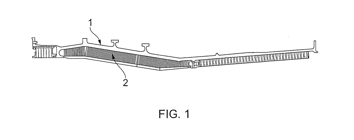
[0049]For illustrative purposes, FIG. 1 shows a section of an upper region of a fan case 1 suitable for use in a gas turbine engine, in which one or more liner panels 2 are bonded directly to the fan case 1. Liner panels 2 may be provided as impact liners, fan track liners etc.

[0050]As discussed above it can be a time consuming and delicate procedure to remove such a liner panel 2, or a section thereof, from the fan case 1 using conventional techniques.

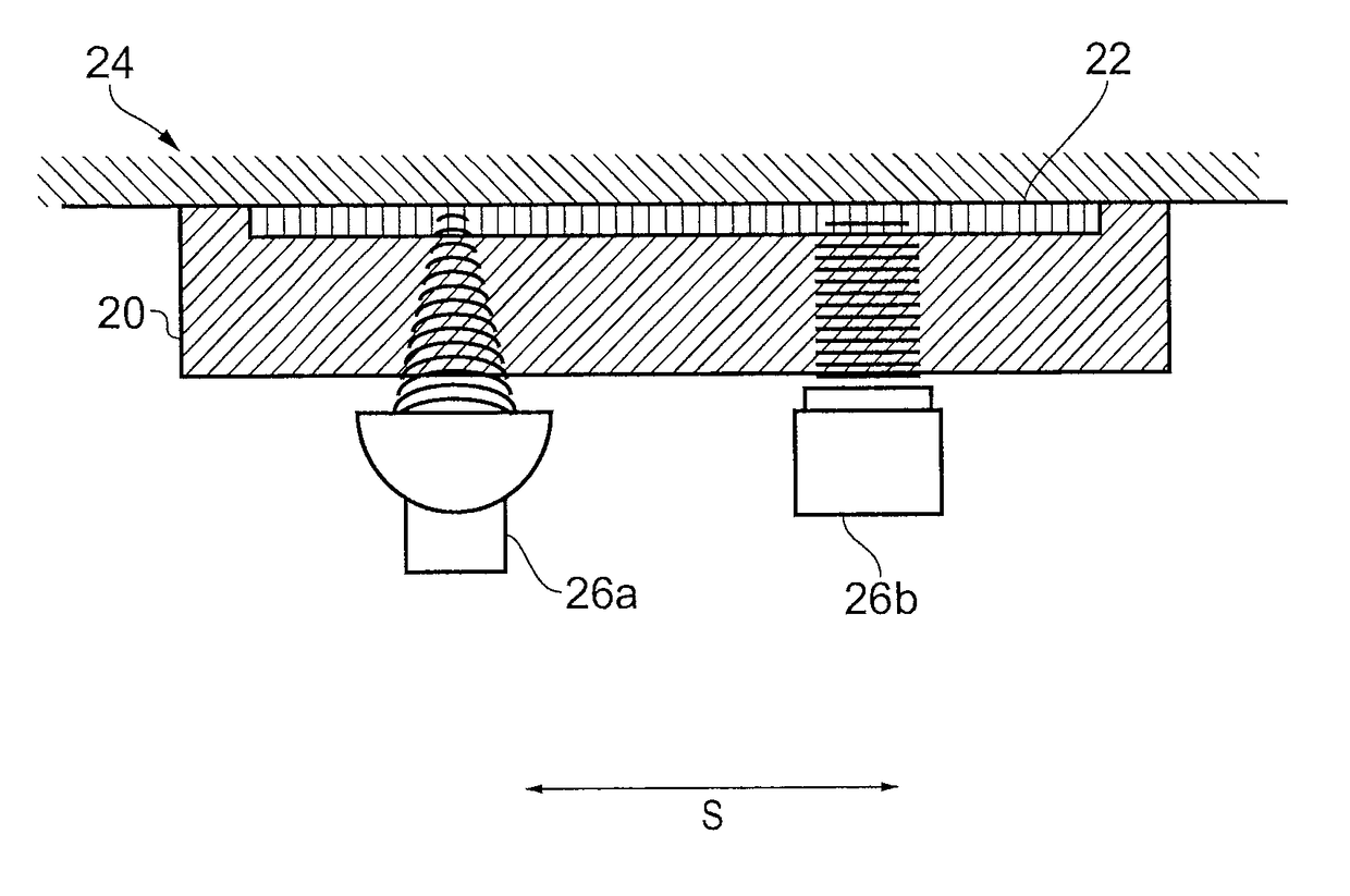
[0051]Therefore, in an aspect, it is proposed to incorporate a bonding patch typically located (radially) between the liner panel 2 and the fan casing 1 to provide for easier and more efficient removal of the liner panel 2 from the fan case. The bonding patch may be bonded to the fan casing by means of an adhesive for example. The bonding patch may be attached to the liner panel by an adhesive or by other means such as mechanical fixings, for example bolts.

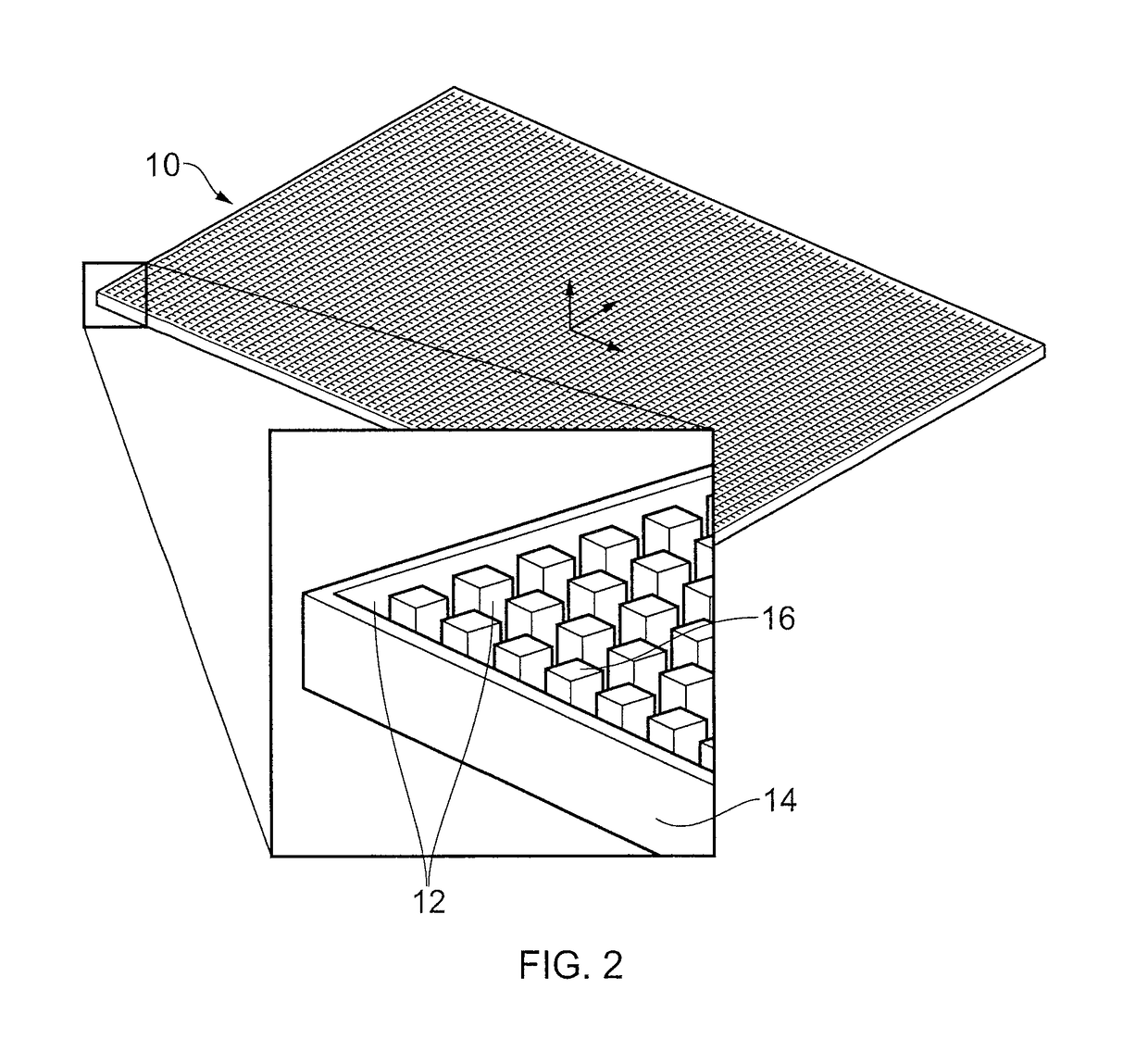
[0052]An embodiment of a bonding patch 10 is shown in FIG. 2.

[0053]Bonding patc...


PUM

PropertyMeasurementUnit
length of timeaaaaaaaaaa
frequencyaaaaaaaaaa
lengthaaaaaaaaaa

Abstract

A gas turbine engine comprising a casing, a bonding patch (10, 22) bonded to a surface of the casing, and a liner attached to the bonding patch. The bonding patch (10, 22) comprising a bonding region (12) configured to receive an adhesive for bonding the patch (10, 22) to a surface. A plurality of de-bonding elements (16) is configured to be movable relative to the bonding region (12) in response to an energizing signal.

Description

FIELD OF THE INVENTION[0001]The present invention relates to a bonding patch which is de-bondable from a surface in response to the application of an energising signal such as a sound wave or an electrical signal; in particular, but not exclusively, to a bonding patch for bonding a liner (e.g. fan track liner) to a case (e.g. fan case) of a gas turbine engine.BACKGROUND OF THE INVENTION[0002]Typically, in gas turbine engines the impact or fan track liners have been bonded on to the fan case of the engine. In the past, this has been done in a large oven using a hot curing adhesive. Advantageously, bonding is a simple solution requiring minimal part count, minimal additional features on the case and is a relatively well understood process.[0003]However, removal of the bonded liners from the case is not trivial. Removal of the liners may be necessary for repair / replacement reasons. In the past it has been proposed that sections of the liners can be cut and chiseled out to expose the ba...

Claims


Application Information

Patent Timeline
Patent Type & Authority Patents(United States)
IPC IPC(8): F01D25/28F01D25/24F16B11/00
CPCF01D25/28F01D25/24F01D25/246F16B11/006F05D2260/407F05D2220/32F05D2230/70F05D2260/32C09J7/40B23P6/002B29C65/76B29C73/10F01D11/12
Inventor BENSON, CHRISTOPHER
Owner ROLLS ROYCE PLC
Learn More