System and method for determination of object volume with multiple three-dimensional sensors

a three-dimensional sensor and object volume technology, applied in the field of machine vision systems, to achieve the effect of accurate determination of the volume of the obj

Active Publication Date: 2018-09-11
COGNEX CORP
View PDF22 Cites 16 Cited by
  • Summary
  • Abstract
  • Description
  • Claims
  • Application Information

AI Technical Summary

Benefits of technology

[0009]This invention overcomes disadvantages of the prior art by providing a system and method for determination of object volume that employs at least two displacement sensors arranged so that the fields of view (FOVs) of the displacement sensors collectively image the features needed/desired to accurately determine the volume of the object. Illustratively, a calibration object (e.g. a frustum) is used at training time to define planes in physical space in the views of the two or more displacement sensors. Respective synthetic range images are generated from the calibration object images, which represent the volumes in the area between those planes and the far field of the sensors' view—wherein each sensor has its own respective range image. During runtime, each displacement sensor acquires an actual, runtime ran

Problems solved by technology

A particular challenge is measuring the volume of an object that includes su

Method used


Image

  • System and method for determination of object volume with multiple three-dimensional sensors
  • System and method for determination of object volume with multiple three-dimensional sensors
  • System and method for determination of object volume with multiple three-dimensional sensors

Examples


Embodiment Construction

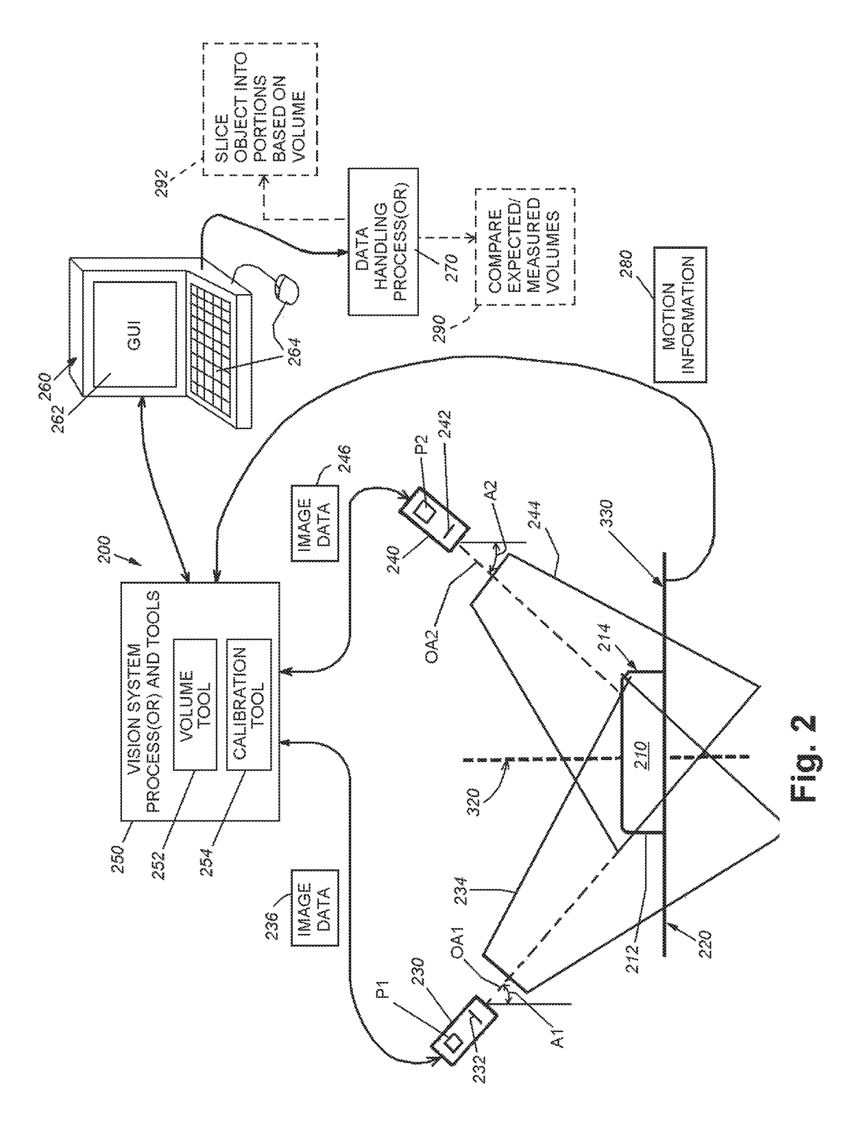
[0024]FIG. 2 is a diagram of a vision system arrangement 200 shown acquiring an image of a runtime object 220 placed on a moving platform or conveyor 220 (an operating surface). A plurality (at least two) 3D sensors 230 and 240 are arranged to image the object 210 so that their respective optical axes OA1 and OA2 provide fields of view (FOVs) that effectively image all features (e.g. sides 212 and 214) that would otherwise fail to provide accurate volumetric information when imaged by a single displacement sensor's FOV. As described above, the 3D sensors utilized herein can be based upon a variety of technologies. By way of non-limiting example, the 3D sensors shown and described are laser displacement sensors (also termed, simply “displacement sensors”); however, this term can be used to describe a 3D sensor that is based upon any appropriate technology or technical principle of operation. The number of displacement sensors arranged to image the object is highly variable and is in ...


PUM


Abstract

A system and method for determining volume of a runtime object with a vision system is provided. A plurality of vision sensors are arranged so that the fields of view (FOVs) of the plurality of vision sensors collectively view features associated with volume determination of a runtime object. Each of the displacement sensors generates range images from sequences of analyzed images, each producing a single row of the range image. An ignoring volume is subtracted from the measured range image based upon one or more dividing planes as they appear in the viewing/imaging perspective of each displacement sensor. Negative subtraction results are substantially nulled. The resulting representative range images are used to calculate the volume of a portion of the object, as sectioned by the diving planes. Each volume result is summed/added to derive the overall summed volume of the runtime object.

Description

RELATED APPLICATION[0001]This application claims the benefit of U.S. Provisional Application Ser. No. 62 / 188,732, entitled SYSTEM AND METHOD FOR DETERMINATION OF OBJECT VOLUME WITH MULTIPLE THREE-DIMENSIONAL SENSORS, filed Jul. 5, 2015, the teaching of which are expressly incorporated herein by reference.FIELD OF THE INVENTION[0002]This invention relates to machine vision systems used in determining the volume of an imaged object surface using a three-dimensional (3D) sensor.BACKGROUND OF THE INVENTION[0003]In manufacturing and assembly processes, it is often desirable to analyze an object surface to determine the nature of features and / or irregularities. The displacement (or “profile”) of the object surface can be determined using a machine vision system (also termed herein “vision system”) in the form of a laser displacement sensor (also termed a laser beam “profiler”). A laser displacement sensor captures and determines the (three dimensional) profile of a scanned object surface ...

Claims


Application Information

Patent Timeline
IPC IPC(8): G06K9/32G06T7/00G06T7/60G01B11/25G01S17/89G06T7/62G01S17/87
CPCG06T7/602G01B11/2518G01S17/89G06T7/0004G06T7/0081G06T7/62G06T2207/10012G06T2207/30164G01B2210/52G06T2207/10028G06T2207/20224G06T7/194G01B11/00G01B11/245G01B11/25G01S17/87
Inventor REOME, MATTHEW R.JOHNSON, MARK D.AKOPYAN, MIKHAIL
Owner COGNEX CORP
Why Eureka
Try Eureka