Gas detection flow rate controller

a flow rate controller and gas detection technology, applied in the direction of liquid/fluent solid measurement, volume metering, instruments, etc., can solve the problems of inaccurate flow restrictors, generating erroneous gas composition measurements, and flow restrictors that do not provide real-time feedback and/or adjustability

Inactive Publication Date: 2018-09-18
USA REPRESENTED BY THE SEC OF THE NAVY
View PDF7 Cites 0 Cited by
  • Summary
  • Abstract
  • Description
  • Claims
  • Application Information

AI Technical Summary

Benefits of technology

[0005]Another object of the present invention is to provide a flow rate control apparatus that can provide feedback on the flow rate of a gas being supplied to a gas detection tube.

Problems solved by technology

Unfortunately, flow restrictors can be inaccurate when it comes to flow rate thereby generating erroneous gas composition measurements.
In addition, flow restrictors do not provide real-time feedback and / or adjustability with respect to a gas's flow rate.

Method used


Image

  • Gas detection flow rate controller
  • Gas detection flow rate controller
  • Gas detection flow rate controller

Examples


Embodiment Construction

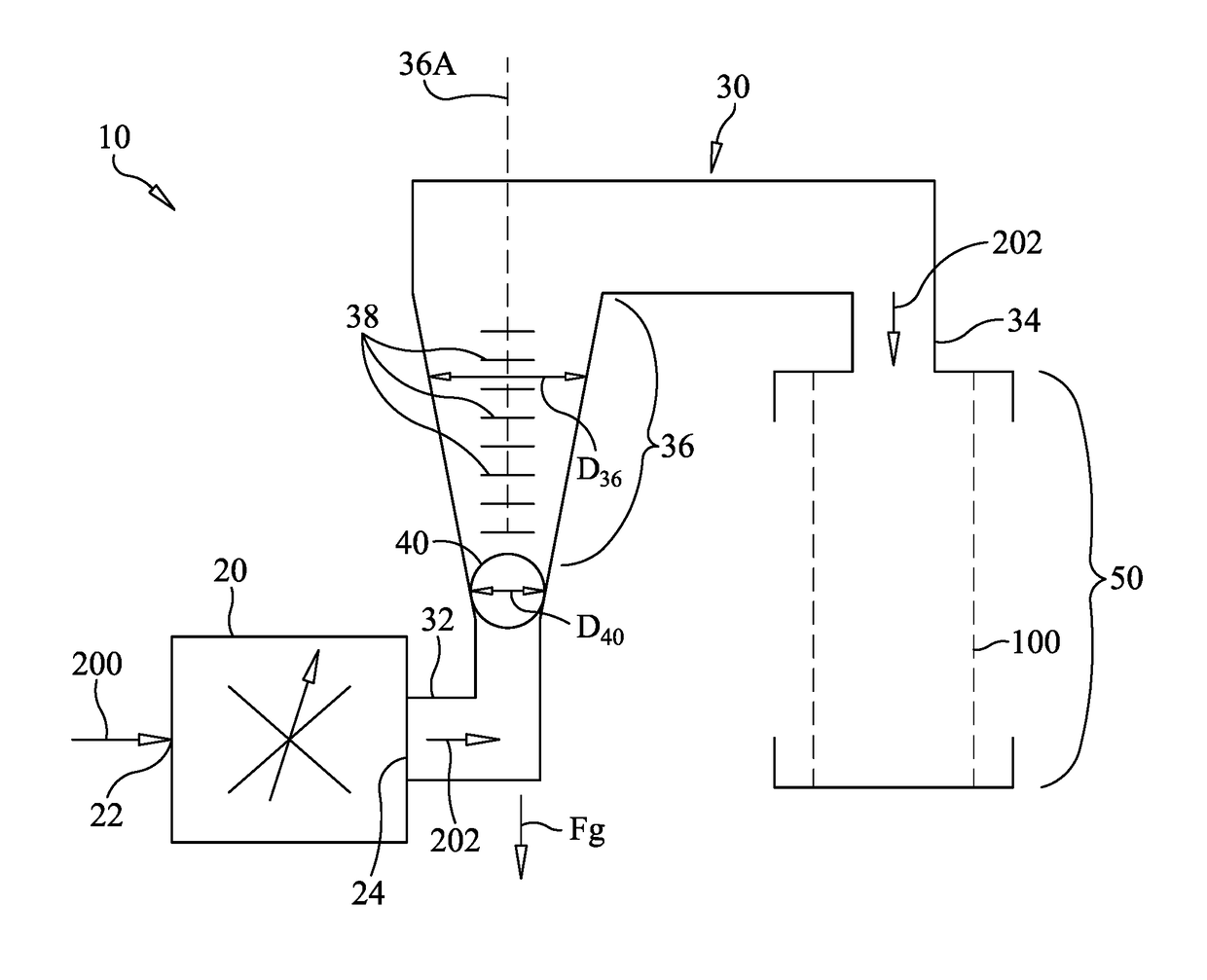
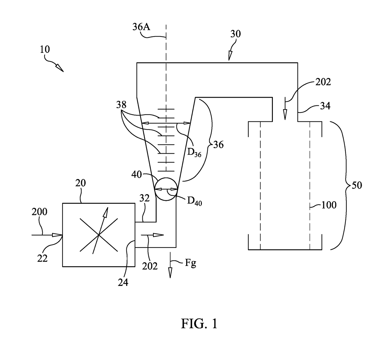
[0013]Referring now to the drawings and more particularly to FIG. 1, a flow rate control apparatus for controlling the flow rate of a gas being supplied to a gas detection tube in accordance with an embodiment of the present invention is shown and is referenced generally by numeral 10. The gas detection tube, illustrated by dashed lines 100, is not part of flow rate control apparatus 10. As is known in the art, gas detection tube 100 contains material (not shown) that reacts with a specified flow rate of a gas in order to produce a visual change in the material (e.g., color change) when a particular gas component is present in the gas in a specified quantity. Flow rate control apparatus 10 allows a user to provide and adjust the gas's specified flow rate as well as monitor the flow rate during the course of a test.

[0014]Flow rate control apparatus 10 includes an adjustable valve 20, a conduit30, a ball / float 40 disposed in conduit 30, and a tube support 50 for holding gas detection ...


PUM

PropertyMeasurementUnit
forceaaaaaaaaaa
gravityaaaaaaaaaa
transparentaaaaaaaaaa

Abstract

A flow rate control apparatus includes an adjustable valve receiving a flow of a gas. A conduit has a first end coupled to the valve. The conduit includes a translucent or transparent portion thereof whose longitudinal axis is adapted to be aligned with a force of gravity with a visual scale being disposed on the translucent/transparent portion. The visual scale is indicative of gas flow rates moving through the conduit. A ball disposed in the translucent/transparent portion has an outer diameter that is less than an inner diameter of the translucent/transparent portion. A tube support, coupled to the second end of the conduit, is adapted to hold a gas detection tube wherein the gas flow flowing around the ball is introduced into the gas detection tube from the second end of the conduit.

Description

ORIGIN OF THE INVENTION[0001]The invention described herein may be manufactured and used by or for the Government of the United States of America for Governmental purposes without payment of any.FIELD OF THE INVENTION[0002]The invention relates generally to gas flow controllers, and more particularly to a flow rate control apparatus for controlling the flow rate of a gas being supplied to a gas detection tube.BACKGROUND OF THE INVENTION[0003]The U.S. Navy currently uses high-pressure compressor assemblies to recharge Self-Contained Breathing Apparatus (SCBA) aboard its ships. The recharge of SCBAs requires Compressed Gas Association (CGA) grade “d” air which can only be supplied by a compressor that is approved to this standard as evidenced by quarterly air sample checks. Compressor air testing uses gas detection tubes to check air composition produced by the compressor that is ultimately to be used to sustain life in hazardous environments. Testing requirements include determining ...

Claims


Application Information

Patent Timeline
Patent Type & Authority Patents(United States)
IPC IPC(8): G01F1/28G01N1/22
CPCG01F1/28G01N1/2226G01N2001/2238G01F1/22G01F1/26G01F15/002G01F15/005
Inventor BOTTOMY, CHRISBLACK, MARSHALLSMITH, CHRIS
Owner USA REPRESENTED BY THE SEC OF THE NAVY
Why Eureka
Try Eureka