Phasing an optical interferometer using the radio emission from the target being observed

an optical interferometer and target technology, applied in the field of target detection and characterization, can solve the problems of imposing a sensitivity limit that is further complicated, difficult to build signal strength, and the resolution of the largest ground-based optical telescope is generally not good,

Active Publication Date: 2018-09-25
THE UNITED STATES OF AMERICA AS REPRESENTED BY THE SECRETARY OF THE NAVY
View PDF1 Cites 3 Cited by
  • Summary
  • Abstract
  • Description
  • Claims
  • Application Information

AI Technical Summary

Problems solved by technology

However, the largest ground-based optical telescopes generally cannot reach resolutions better than approximately 50 mas.
One of the challenges with using an optical / infrared interferometer is the phasing of the different telescopes in the array to coherently combine the light from these telescopes.
This time limitation imposes a sensitivity limit that is further complicated by each of low target brightness and low fringe amplitudes due to the target structure, particularly for the long baselines (separations between telescopes) that are needed to image target details.
This sensitivity limit makes it difficult to build signal strength by integrating the signal over time.
Although optical / infrared interferometry has reached resolutions better than 1 mas in observing astronomical targets, conventional optical / infrared interferometers are generally not capable of observing geosats, because they are approximately 10,000 times fainter than astronomical targets of the same apparent size.
In addition, the appearance of a geosat is dominated by large-scale structures, leading to low-amplitude interference fringes when observed with long interferometry baselines needed to detect small-scale details.
Currently, there is no ground based facility capable of imaging geosats with a resolution better than 25 to 50 mas, which corresponds to dimensions of approximately four to eight meters at the distance of geosats.

Method used


Image

  • Phasing an optical interferometer using the radio emission from the target being observed
  • Phasing an optical interferometer using the radio emission from the target being observed
  • Phasing an optical interferometer using the radio emission from the target being observed

Examples


Embodiment Construction

[0033]The embodiments herein and the various features and advantageous details thereof are explained more fully with reference to the non-limiting embodiments that are illustrated in the accompanying drawings and detailed in the following description. Descriptions of well-known components and processing techniques are omitted so as to not unnecessarily obscure the embodiments herein. The examples used herein are intended merely to facilitate an understanding of ways in which the embodiments herein may be practiced and to further enable those of skill in the art to practice the embodiments herein. Accordingly, the examples should not be construed as limiting the scope of the embodiments herein.

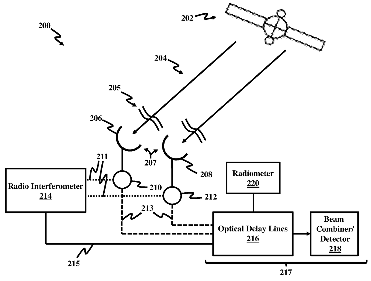
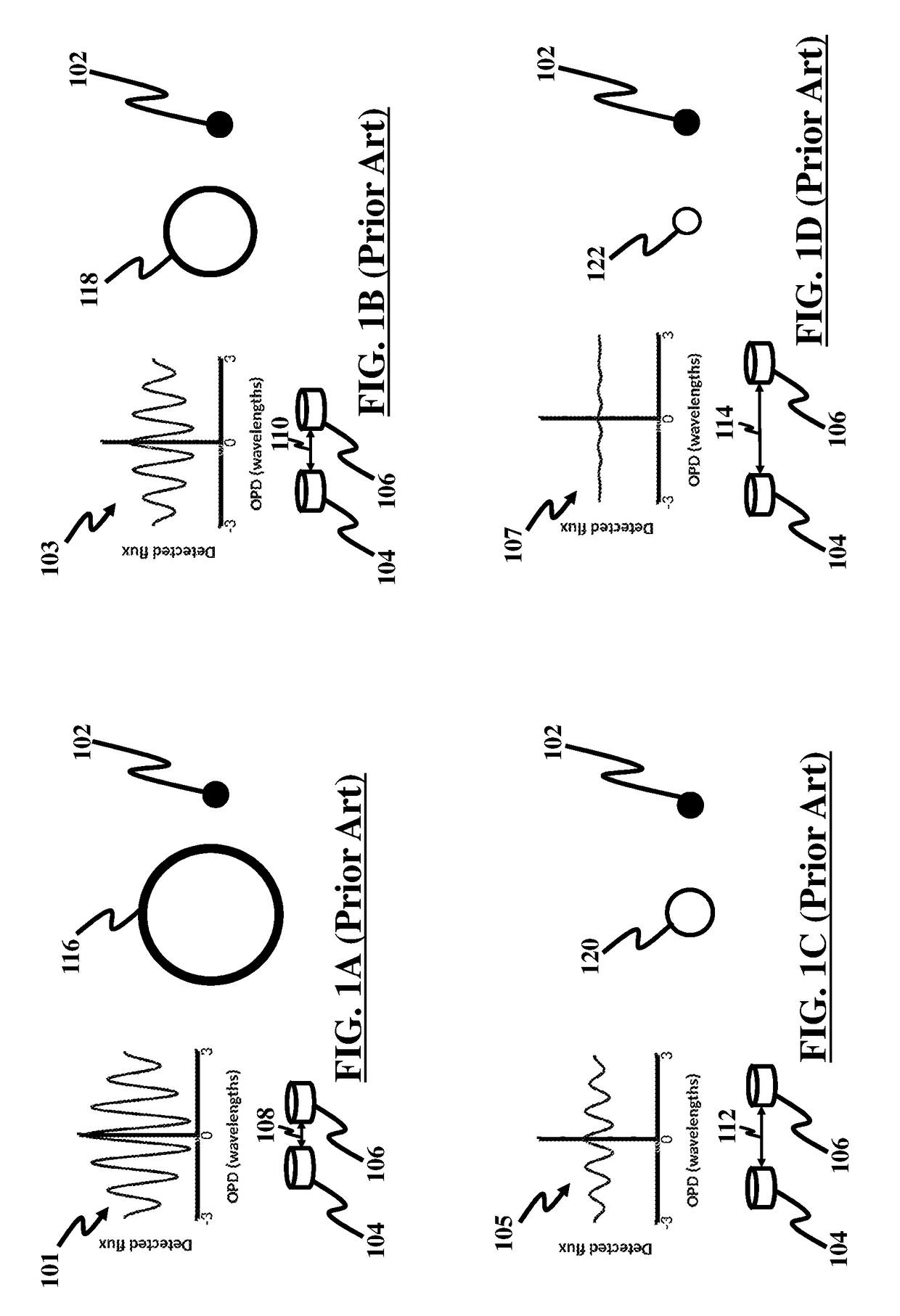
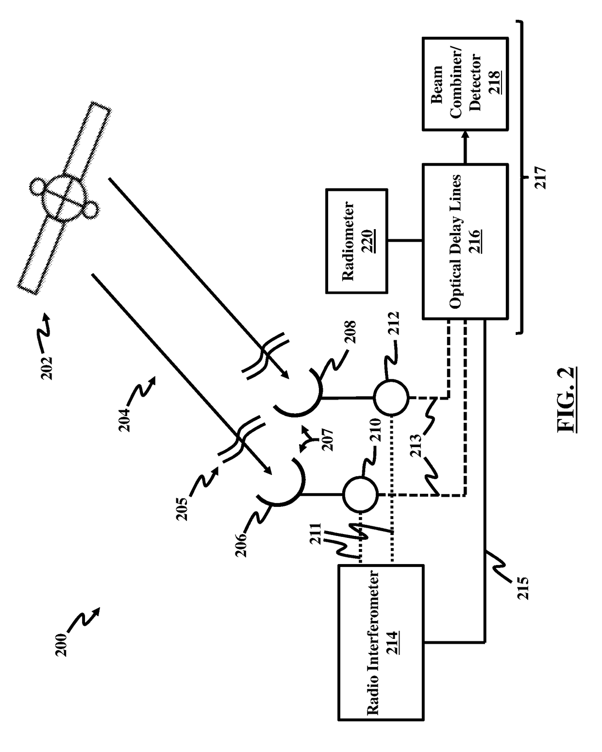
[0034]An embodiment herein provides a technique to phase an optical or infrared interferometer composed of two or more optical or infrared telescopes. The optical or infrared interferometer may be used to observe a geostationary satellite (geosat), or other objects in space, by receiving reflec...


PUM


Abstract

An interferometry system including a first telescope for simultaneously receiving a first optical / infrared signal and a first radio signal from a target; a second telescope configured to simultaneously receive a second optical / infrared signal and a second radio signal from the target; a first beam splitter communicatively connected to the first telescope, where the first beam splitter is configured to separate the first optical / infrared signal from the first radio signal; a second beam splitter communicatively connected to the second telescope, where the second beam splitter is configured to separate the second optical / infrared signal from the second radio; and a first optical / infrared interferometer configured to detect an interferometry image of the target using the first and second optical / infrared and radio signals.

Description

CROSS REFERENCE TO RELATED APPLICATION[0001]This application claims the benefit of U.S. Provisional Patent Application No. 62 / 302,846 filed on Mar. 3, 2016, the contents of which, in its entirety, is herein incorporated by reference.GOVERNMENT INTEREST[0002]The embodiments herein were made by employees of the United States Government and may be manufactured, used, and / or licensed by or for the United States Government without the payment of royalties thereon.BACKGROUNDTechnical Field[0003]The embodiments herein generally relate to target detection and characterization, and more particularly to using any of optical and infrared interferometry for target detection and characterization.Description of the Related Art[0004]It is desirable to observe and image geostationary satellites (geosats) from the ground. This capability would serve multiple purposes, such as surveillance, detection of companion satellites, and monitoring the health of these highly-valued assets. Geosats orbit at al...

Claims


Application Information

Patent Timeline
Patent Type & Authority Patents(United States)
IPC IPC(8): G01B9/02G01S3/14G02B5/00G01S3/48
CPCG01B9/02019G01S3/14G02B5/00G01S3/48G01B2290/10G02B27/1006
Inventor SCHMITT, HENRIQUEMOZURKEWICH, DAVIDARMSTRONG, JOHN THOMASRESTAINO, SERGIO R.
Owner THE UNITED STATES OF AMERICA AS REPRESENTED BY THE SECRETARY OF THE NAVY
Why Eureka
Try Eureka