Variable gap hard stop design

a technology of variable gap and hard stop, which is applied in the direction of coating, chemical vapor deposition coating, metallic material coating process, etc., can solve the problem of variable gap between the susceptor and the base pla

Active Publication Date: 2018-10-02
ASM IP HLDG BV
View PDF1440 Cites 319 Cited by
  • Summary
  • Abstract
  • Description
  • Claims
  • Application Information

AI Technical Summary

Problems solved by technology

Interaction between the susceptor and the baseplate results in a variable gap between the susceptor and the baseplate.

Method used


Image

  • Variable gap hard stop design
  • Variable gap hard stop design
  • Variable gap hard stop design

Examples


Embodiment Construction

[0035]Although certain embodiments and examples are disclosed below, it will be understood by those in the art that the invention extends beyond the specifically disclosed embodiments and / or uses of the invention and obvious modifications and equivalents thereof. Thus, it is intended that the scope of the invention disclosed should not be limited by the particular disclosed embodiments described below.

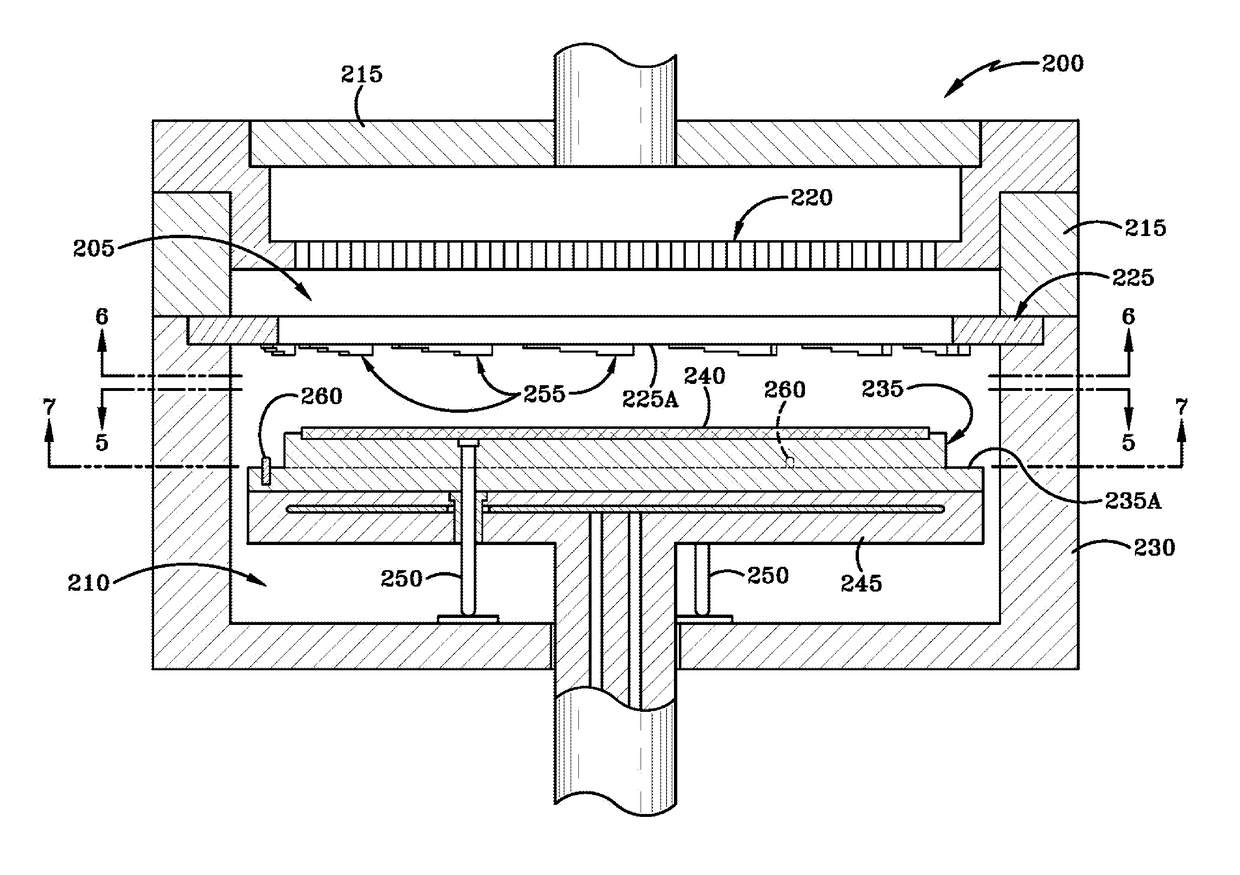
[0036]FIG. 4 illustrates a reaction system 200 according to at least one embodiment of the invention. The reaction system 200 includes a reaction region 205 and a substrate loading region 210. The reaction region 205 is defined in part by a reaction region housing 215, a reactant distribution system 220, and a baseplate 225. The substrate loading region 210 is defined in part by a substrate loading housing 230. The reactant distribution system 220 is responsible for passing a gaseous reactant over a substrate to allow for deposition of the reactant material. As illustrated, the reactan...


PUM

PropertyMeasurementUnit
heightaaaaaaaaaa
heightaaaaaaaaaa
heightaaaaaaaaaa

Abstract

A reaction system for processing semiconductor substrates is disclosed. The reaction system includes a susceptor for holding the substrate as well as a baseplate as a part of housing for the reaction system. A pin located on the susceptor can interact with a baseplate feature located on the baseplate to result in a variable gap between the susceptor and the baseplate. The baseplate feature may take the form of a series of steps, a wedge, or a milled-out feature.

Description

FIELD OF INVENTION[0001]The present disclosure generally relates to semiconductor processing tools. More particularly, the disclosure relates to a wafer handling mechanism comprising a susceptor and a baseplate of a reaction region.BACKGROUND OF THE DISCLOSURE[0002]Semiconductor processing typically involves fabrication of devices, such as transistors, diodes, and integrated circuits, upon a thin piece of semiconductor material called a substrate. The semiconductor processing takes place in a reaction region, where gases are passed over the substrate, resulting in a controlled deposit of material upon the substrate. The substrate is lifted into the reaction region by a susceptor.[0003]FIG. 1 illustrates such a prior art reaction system 100. The reaction system 100 includes a reaction region 105 and a substrate loading region 110. The reaction region 105 is defined by a reaction region housing 115 and a reactant distribution system 120. The reactant distribution system 120 is illustr...

Claims


Application Information

Patent Timeline
Patent Type & Authority Patents(United States)
IPC IPC(8): H01L21/687C23C16/44C23C16/458
CPCC23C16/4588C23C16/4401H01L21/68785H01L21/68735C23C16/4412H01L21/6835H01L21/68764H01L21/68792
Inventor SCHMOTZER, MICHAELWHALEY, SHAWN
Owner ASM IP HLDG BV
Why Eureka
Try Eureka