Pressed pulley

a technology of pressed pulleys and pulleys, which is applied in the direction of gearing, gearing elements, hoisting equipments, etc., can solve the problem of inability to increase the load capacity, and achieve the effect of increasing the load capacity of the pulley

Active Publication Date: 2018-10-02
NTN CORP
View PDF85 Cites 15 Cited by
  • Summary
  • Abstract
  • Description
  • Claims
  • Application Information

AI Technical Summary

Benefits of technology

[0014]According to the present invention, since the outer tubular portion and the inner tubular portion are connected together by a U-shaped annular bent portion formed with an inner circular arc-shaped surface having a constant radius of curvature and connected to a radially inner surface of the outer tubular portion such that the radially inner surface extends in a first tangential direction of the inner circular arc-shaped surface, and connected to a radially outer surface of the inner tubular portion such that the radially outer surface extends in a second tangential direction of the inner circular arc-shaped surface, it is possible to increase the inner diameter of the inner tubular portion without increasing the outer diameter of the outer tubular portion. This in turn makes it possible to increase the load capacity of the pulley.
[0012]Preferably, the pressed pulley has a wall thickness t which is within a range of 70 to 95% of the wall thickness T of a steel sheet from which the pressed pulley is formed by pressing. With this arrangement, it is possible to improve the dimensional accuracy by adding a cold ironing step. From the above description, it can also be seen that, because t=0.7T to 0.95T and (as noted above) Ri=0.2T to 0.5T, the radius of curvature Ri of the inner circular arc-shaped surface of the connecting portion is in a range of 0.21T to 0.71T (i.e., 0.20 / 0.95t to 0.50 / 0.70t).
[0013]Preferably, a steel sheet from which the pressed pulley is formed by pressing has a wall thickness t within a range of 1.6 to 4.0 mm. The pressed pulley thus formed is high in rigidity, which makes it possible to significantly increase the load capacity.
[0014]According to the present invention, since the outer tubular portion and the inner tubular portion are connected together by a U-shaped annular bent portion formed with an inner circular arc-shaped surface having a constant radius of curvature and connected to a radially inner surface of the outer tubular portion such that the radially inner surface extends in a first tangential direction of the inner circular arc-shaped surface, and connected to a radially outer surface of the inner tubular portion such that the radially outer surface extends in a second tangential direction of the inner circular arc-shaped surface, it is possible to increase the inner diameter of the inner tubular portion without increasing the outer diameter of the outer tubular portion. This in turn makes it possible to increase the load capacity of the pulley.

Problems solved by technology

If the radius of curvature Ri is larger than 0.5 times the wall thickness T, the inner diameter of the inner tubular portion tends to be too small to mount a large-sized bearing in the pulley, which makes it impossible to increase the load capacity.

Method used


Image

  • Pressed pulley
  • Pressed pulley
  • Pressed pulley

Examples


Embodiment Construction

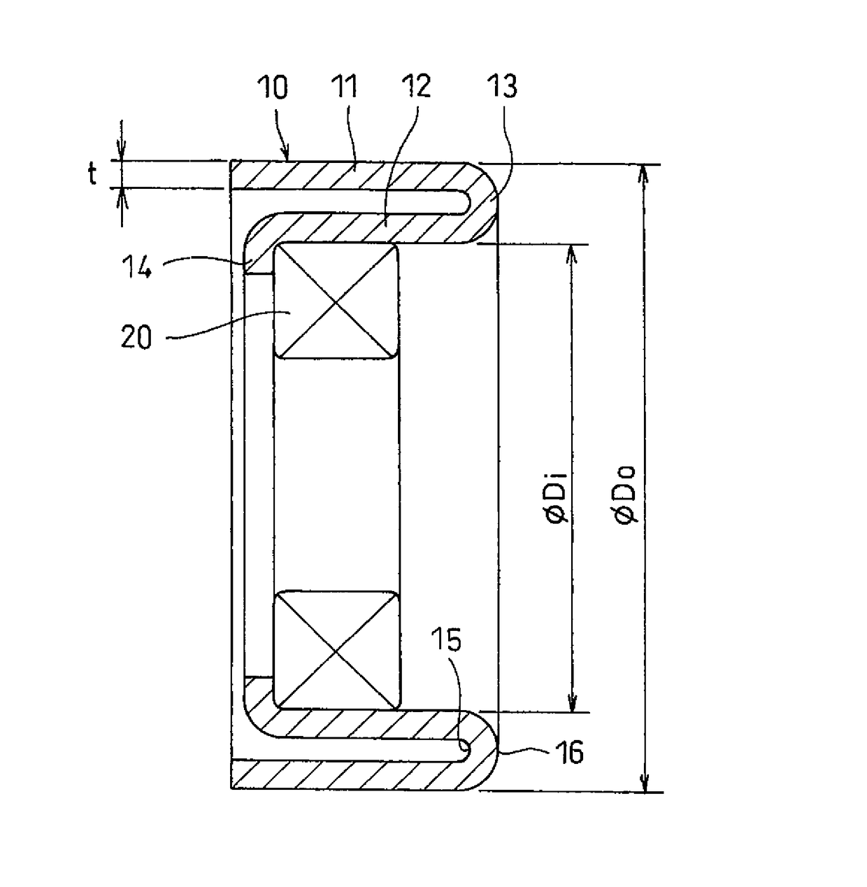
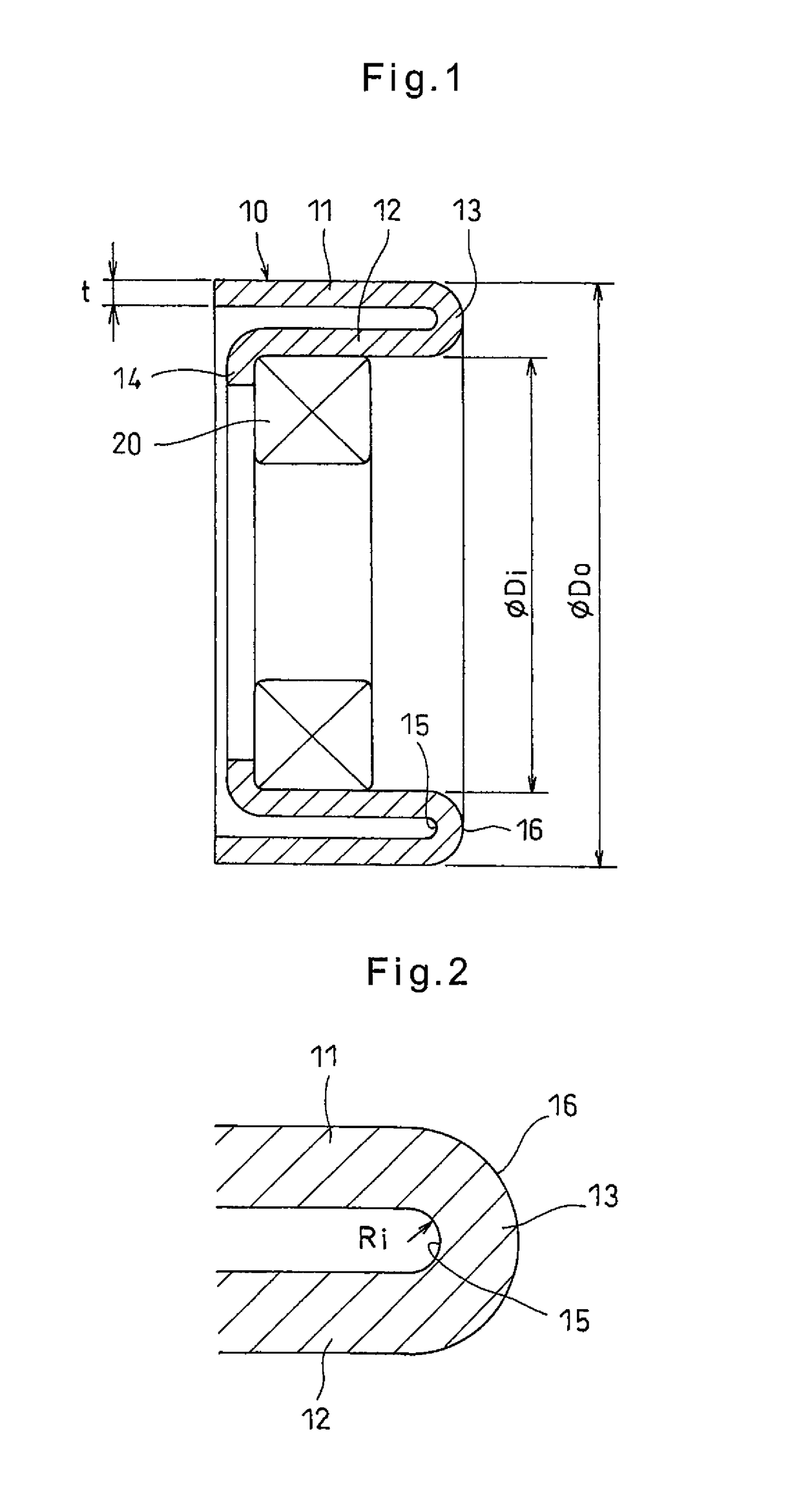
[0018]Now referring to the drawings, the embodiment of the present invention is described. FIGS. 1 and 2 show a pressed pulley 10 embodying the present invention. This pressed pulley 10 is formed by pressing a steel sheet, and includes an outer tubular portion 11 around which a belt is configured to be wound, an inner tubular portion 12 disposed inside the outer tubular portion 11, an annular connecting portion 13 connected to a first end of the inner tubular portion 12 and an end of the outer tubular portion 11, and an inwardly extending flange 14 formed by inwardly bending a second end of the inner tubular portion 12. By mounting a bearing 20 in the inner tubular portion 12, the pressed pulley 10 is used as a tension pulley or an idler pulley.

[0019]The connecting portion 13 is an annularly bent portion having a circular arc-shaped section and formed with an inner circular arc-shaped surface 15 having a constant radius of curvature. The inner circular arc-shaped surface 15 is conne...


PUM


Abstract

A pressed pulley includes an annular connecting portion connected to an end of the outer tubular portion around which a belt is wound and an end of the inner tubular portion. The connecting portion is an annular bent portion having a circular arc-shaped section and formed with an inner circular arc-shaped surface having a constant radius of curvature and connected to the radially inner surface of the outer tubular portion and the radially outer surface of the inner tubular portion through respective tangential lines.

Description

TECHNICAL FIELD[0001]The present invention relates to a pressed pulley formed by pressing a steel sheet.BACKGROUND ART[0002]The below-identified Patent documents 1 and 2 disclose pressed pulleys which are used in tensioners for engine accessory driving belts or timing belts, of automotive engines, or as idler pulleys for adjusting belt winding angles.[0003]The pressed pulley disclosed in Patent document 1 includes a belt winding portion as an outer tubular portion around which a belt is wound, a press-fitting portion as an inner tubular portion provided inside the belt winding portion, and a side plate portion through which the belt winding portion and the press-fitting portion are coupled together. The pressed pulley is formed by pressing a steel sheet such that the winding portion and the press-fitting portion are bent in the same axial direction.[0004]A press-fitting portion-side corner portion provided at the integral portion between the press-fitting portion and the side plate ...

Claims


Application Information

Patent Timeline
Patent Type & Authority Patents(United States)
IPC IPC(8): F16H55/36F16H7/20F16H55/44
CPCF16H55/44
Inventor KODA, TSUYOSHIIZUTSU, TOMOYOSHI
Owner NTN CORP
Why Eureka
Try Eureka