Mounting frame for a switchgear cabinet or a rack

Inactive Publication Date: 2018-10-02
RITTALWERK RUDOLF LOH GMBH & CO KG
View PDF47 Cites 1 Cited by
  • Summary
  • Abstract
  • Description
  • Claims
  • Application Information

AI Technical Summary

Benefits of technology

[0017]A further advantageous embodiment consists in that laterally and in the corner region covering lateral covers and corner covers made of plastic or metal are present which are fixed and/or supported at the mo

Problems solved by technology

Also for such socket adapted to the framework, there are restrictions of design possibilities.
Those known sockets comprise corner piece

Method used


Image

  • Mounting frame for a switchgear cabinet or a rack
  • Mounting frame for a switchgear cabinet or a rack
  • Mounting frame for a switchgear cabinet or a rack

Examples


Embodiment Construction

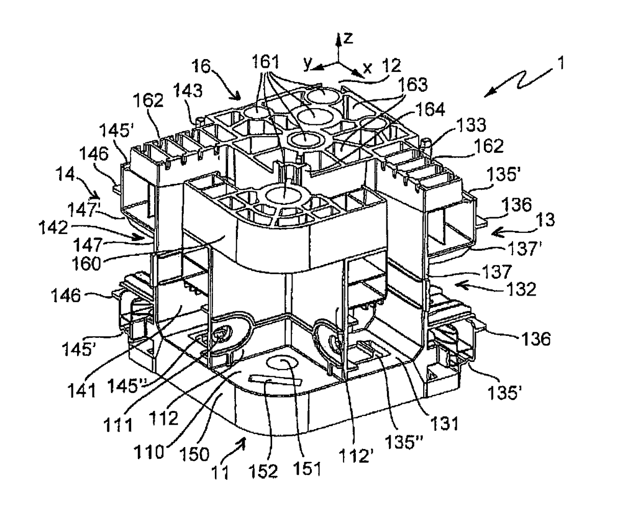
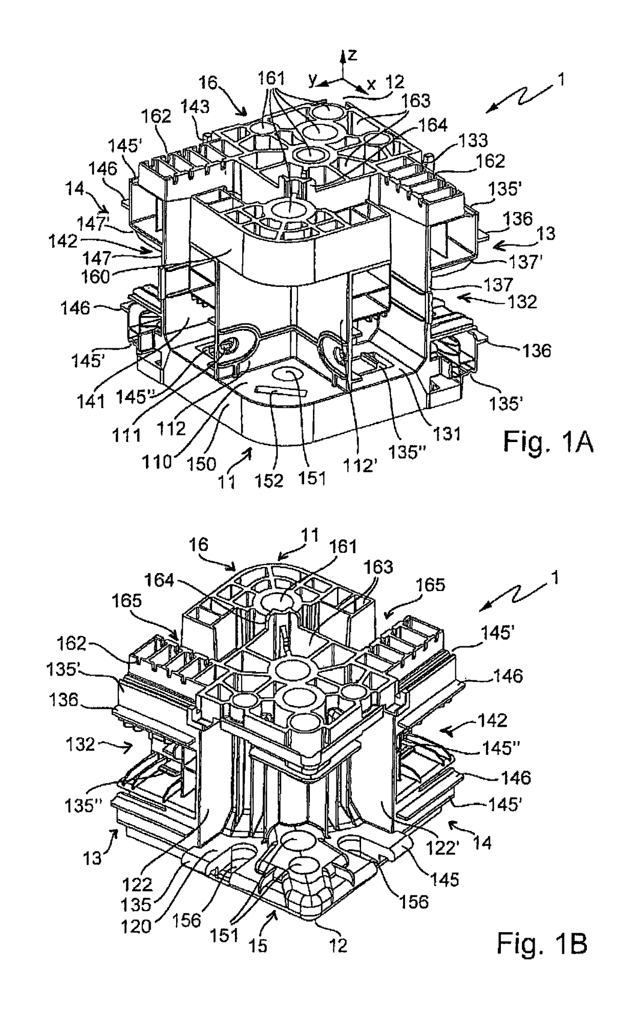
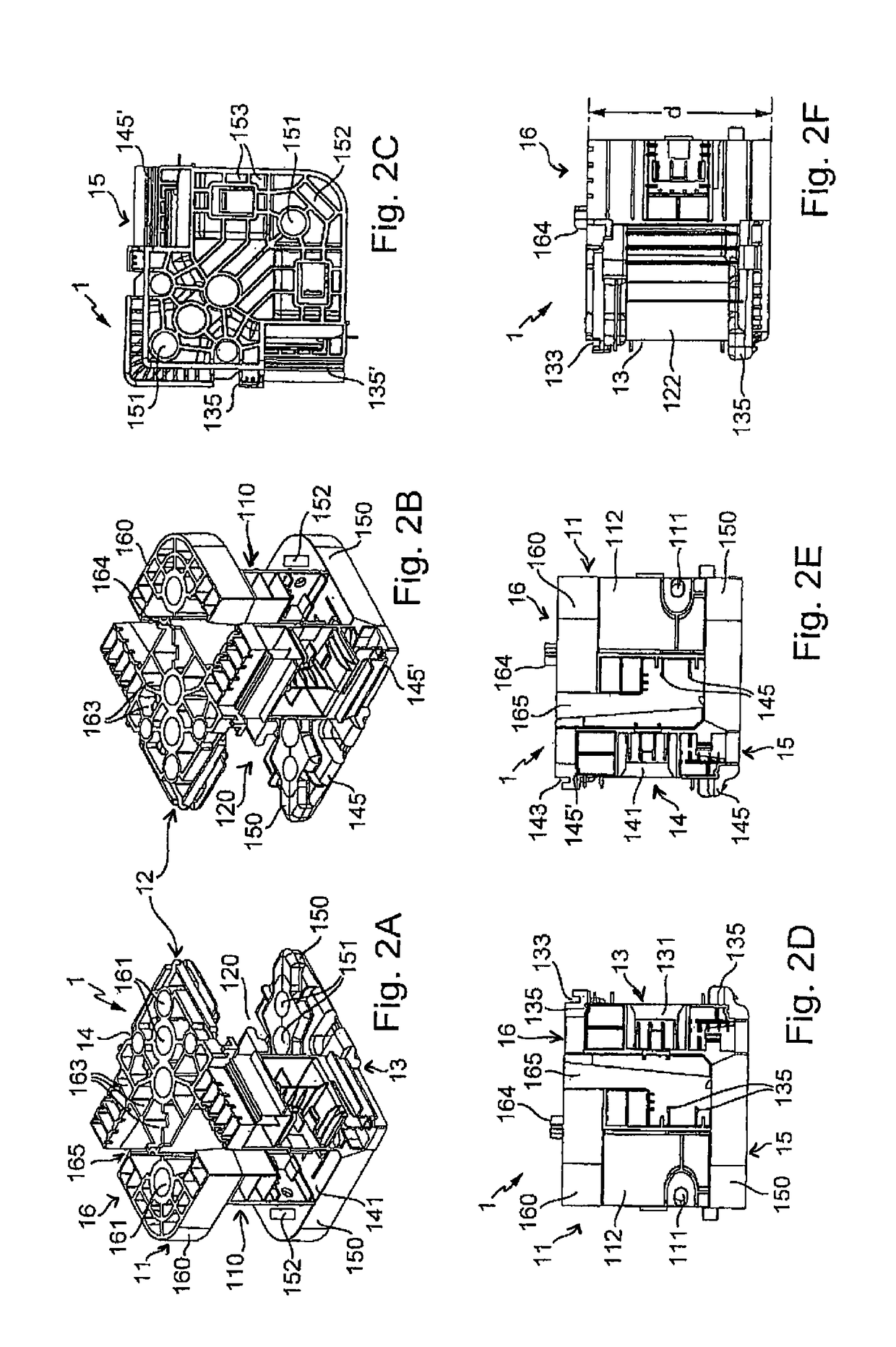
[0071]FIGS. 1A and 1B as well as also FIGS. 2A to 2F and 3A to 3F illustrate a mounting piece 1 in various views. Mounting piece 1 is used as a fundamental construction part of a construction unit, such as e.g. a socket 10 (e.g. FIG. 13 and FIG. 24A) or another mounting frame, for mounting to a switchgear cabinet or rack or another housing, preferably as a corner piece in the corner regions of the construction unit which is preferably rectangular or square in a top view.

[0072]Mounting pieces 1 which are arranged in the corner regions are connected by longitudinal extending intermediate elements, such as mounting rails 32, rails 31 which are C-shaped in cross section (C-rails) and / or lateral covers.

[0073]Mounting piece 1 is formed as a molded part produced in a molding process, preferably as a plastic molded part or alternately as a metal molded part, in particular made of a nonferrous metal, for example of aluminum, or as a molded part of a compound material comprising fiber materia...


PUM


Abstract

A mounting frame for a switchgear cabinet or a rack includes mounting pieces which are arranged, as corner pieces, in the four corner sections of a rectangle or square that extends in an x-y plane, the mounting pieces being produced in a respective shaping process and having outer first and second mounting faces which extend in the x direction and in the y direction at a right angle thereto and which extend in a space direction z at a right angle to the x-y plane, and are provided with hollow spaces which are at least partially surrounded by wall parts and/or bores that are oriented in the z direction. The mounting frame further includes intermediate elements which extend between the mounting pieces in the x direction and in the y direction and the end sections of which are fastened to the mounting pieces. The mounting pieces have wall sections which extend in parallel to the x-y plane, thus making assembly easier.

Description

BACKGROUND OF THE INVENTION[0001]The invention relates to a mounting frame for a switchgear cabinet or a rack, comprising mounting pieces which are arranged, as corner pieces, in the four corner regions of a rectangle or square that extends in an x-y plane, said mounting pieces being produced in a respective shaping process and having outer first and second mounting faces which extend in the x direction and in the y direction at a right angle thereto and which extend in a space direction z at a right angle to the x-y plane, and are provided with hollow spaces which are at least partially surrounded by wall parts and / or bores that are oriented in z direction, and comprising intermediate elements which extend between the mounting pieces in the x direction and in the y direction and the end sections of which are fastened to the mounting pieces.[0002]A mounting frame of this type is disclosed in DE 195 34 551 C1, wherein the mounting frame forms a socket of a switchgear cabinet. In the ...

Claims


Application Information

Patent Timeline
IPC IPC(8): H02B1/30
CPCH02B1/30H02B1/303Y10T403/42F16B2200/67
Inventor BROEMSTRUP, DENNISBOEHME, SIEGFRIEDHOLIGHAUS, HEIKOMUELLER, MATTHIASSCHNAKENBERG, MICHAEL
Owner RITTALWERK RUDOLF LOH GMBH & CO KG
Why Eureka
Try Eureka