Luminous module printed circuit board

A light-emitting module and circuit board technology, which is applied in the direction of circuits, circuit layout, semiconductor devices of light-emitting elements, etc., can solve problems such as design difficulties, and achieve the effects of small material consumption, good thermal conductivity, and contact prevention

Inactive Publication Date: 2014-10-22
OSRAM GMBH
View PDF5 Cites 0 Cited by
  • Summary
  • Abstract
  • Description
  • Claims
  • Application Information

AI Technical Summary

Problems solved by technology

This clearly makes it difficult in practice to use the same component design for such LED modules

Method used


Image

  • Luminous module printed circuit board
  • Luminous module printed circuit board
  • Luminous module printed circuit board

Examples


Embodiment Construction

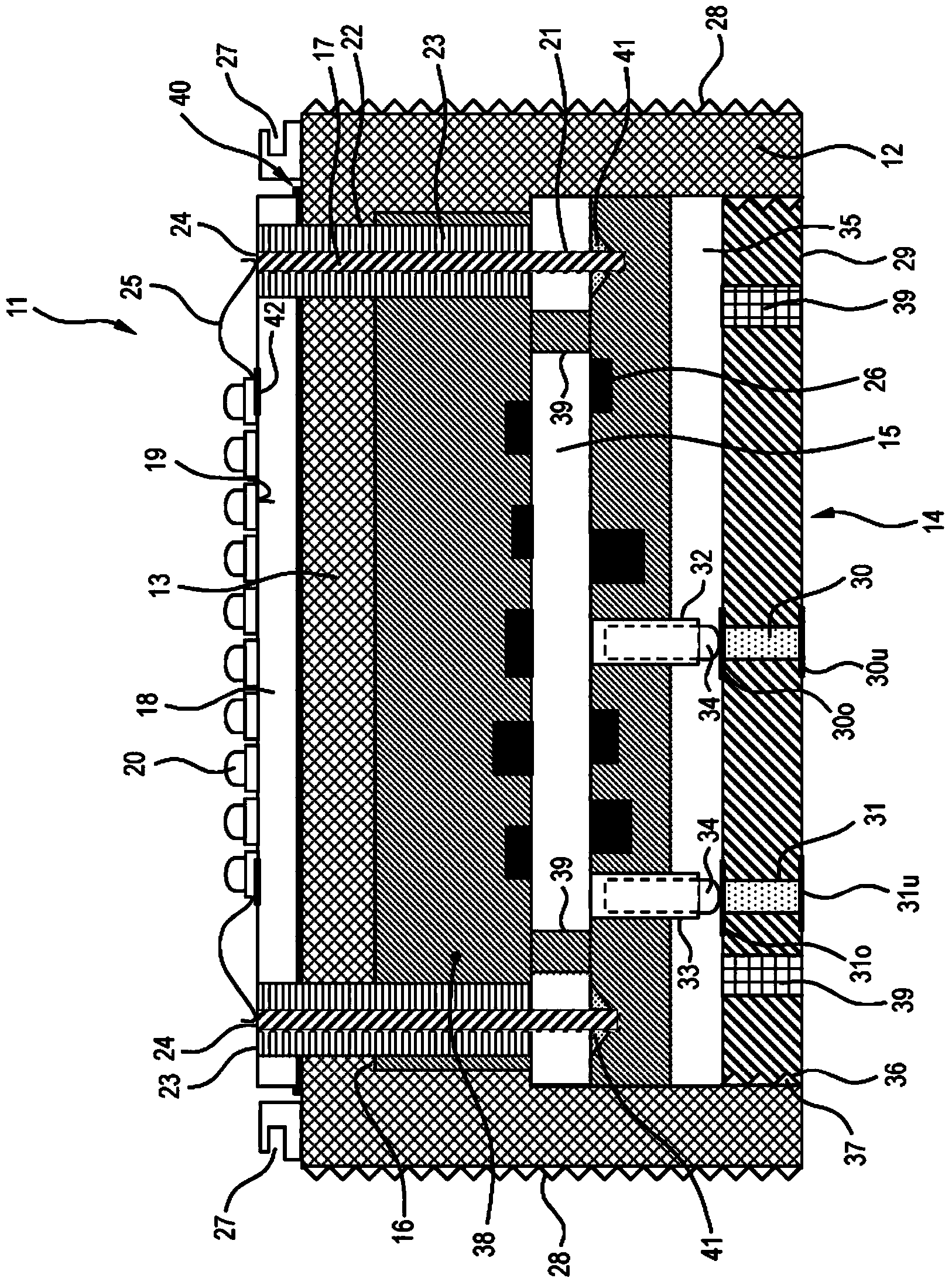
[0052] figure 1 A lighting module 11 is shown for installation in a luminaire, lighting system or the like.

[0053] The lighting module 11 has a metal housing 12 with a hollow cylindrical basic shape with a substantially closed front side 13 and an open rear side 14 . A disc-shaped lighting module circuit board 15 having CEM-3 or FR-4 as its base material is accommodated in the housing 12 . For simple and precise positioning of the light module circuit board 15 , it rests with its front outer edge on the inner projection 16 or on the taper of the housing 12 .

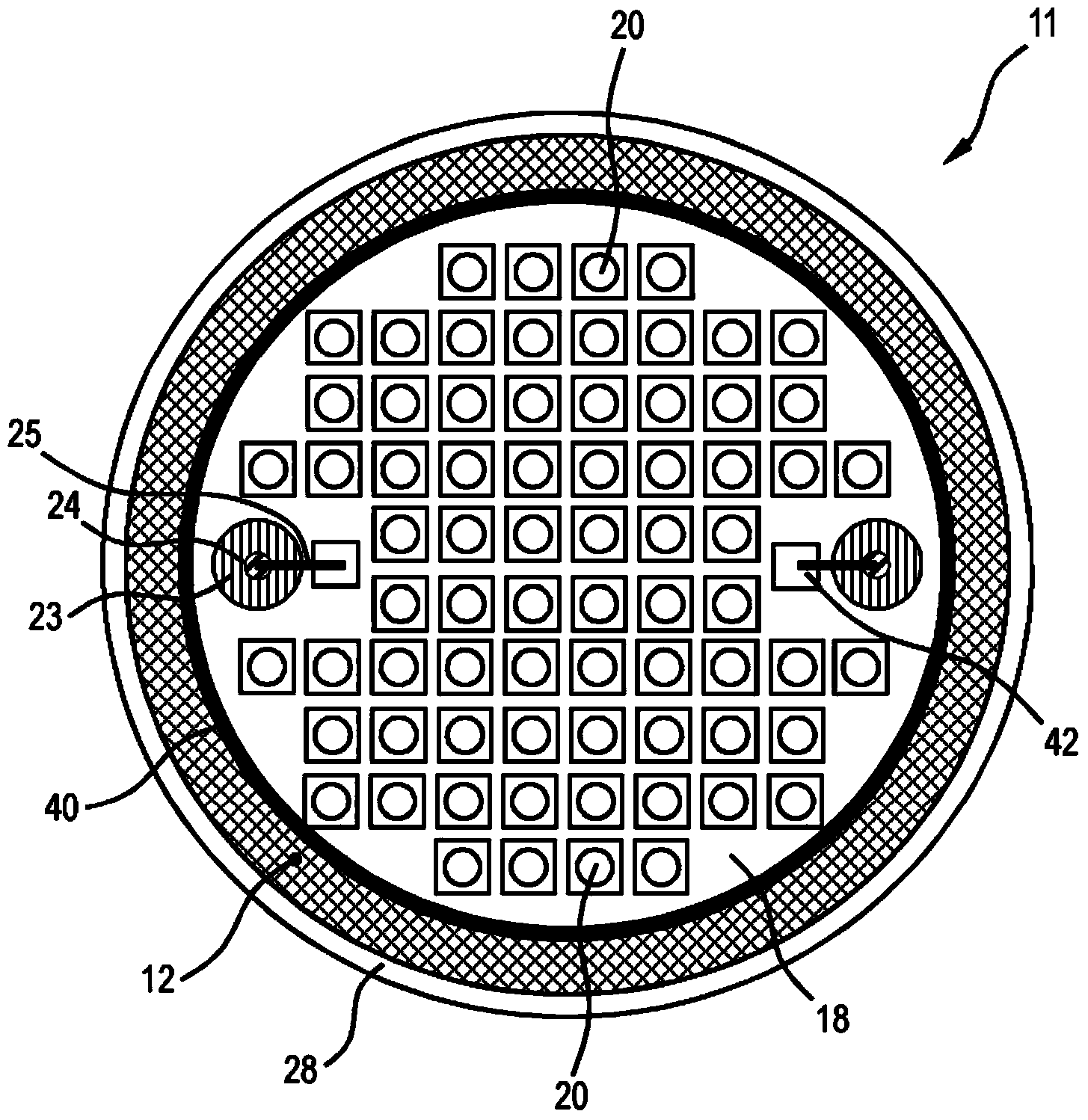
[0054] The lighting module circuit board 15 is electrically connected to the light source substrate 18 via two vertical, electrically conductive contact pins 17 . The light source substrate 18 is arranged outside the housing 12 , that is to say it is placed laterally with its rear side on the front side 13 of the housing 12 , here via a heat-conducting glue 40 . The free front side 19 of the light source substrate 1...


PUM


Abstract

The luminous module printed circuit board (15) is equipped with at least one electrical contact, wherein the at least one electrical contact has at least one spring contact, more particularly spring contact pin (32, 33). A luminous module (11) is equipped with at least one printed circuit board, wherein at least one printed circuit board is a luminous module printed circuit board (15).

Description

technical field [0001] The invention relates to a lighting module circuit board having at least one electrical contact, which is therefore arranged and designed for use with a lighting module. Furthermore, the invention relates to a lighting module having at least one such lighting module printed circuit board. Background technique [0002] To date, light emitting diode (LED) modules have been manufactured in different configurations. This obviously makes it difficult in practice to use identical component designs for such LED modules. The geometric form factor of the LED module is predetermined by the printed circuit board mounted on one side. LED modules comprising multiple circuit boards are usually connected by cable connection means. Contents of the invention [0003] It is the object of the invention to at least partially overcome the disadvantages of the prior art and in particular to provide a lighting module which is better suited for the same component design....

Claims


Application Information

Patent Timeline
Patent Type & Authority Applications(China)
IPC IPC(8): F21V23/00F21K99/00F21Y101/02
CPCH01R12/714H01R13/08F21K9/30F21V23/006F21Y2101/02H01L2224/48091H01L2224/48472F21K9/20F21Y2115/10H01L2924/00014H01L2924/00
Inventor 托马斯·普罗伊施尔迪特尔·艾森赫特
Owner OSRAM GMBH
Why Eureka
Try Eureka