Displacement sensor having a return core in a housing cavity

a technology of displacement sensor and return core, which is applied in the field of displacement sensor, can solve the problems of minor interference in the sensor signal, and achieve the effect of improving the known displacement sensor, cost-effective and robust displacement sensor

Pending Publication Date: 2021-11-18
CONTINENTAL TEVES AG & CO OHG
View PDF2 Cites 0 Cited by
  • Summary
  • Abstract
  • Description
  • Claims
  • Application Information

AI Technical Summary

Benefits of technology

[0005]It is therefore the aspect of the invention to improve the known di...

Problems solved by technology

External magnetic fields are largely conducted past the functional core by ...

Method used


Image

  • Displacement sensor having a return core in a housing cavity
  • Displacement sensor having a return core in a housing cavity
  • Displacement sensor having a return core in a housing cavity

Examples


Embodiment Construction

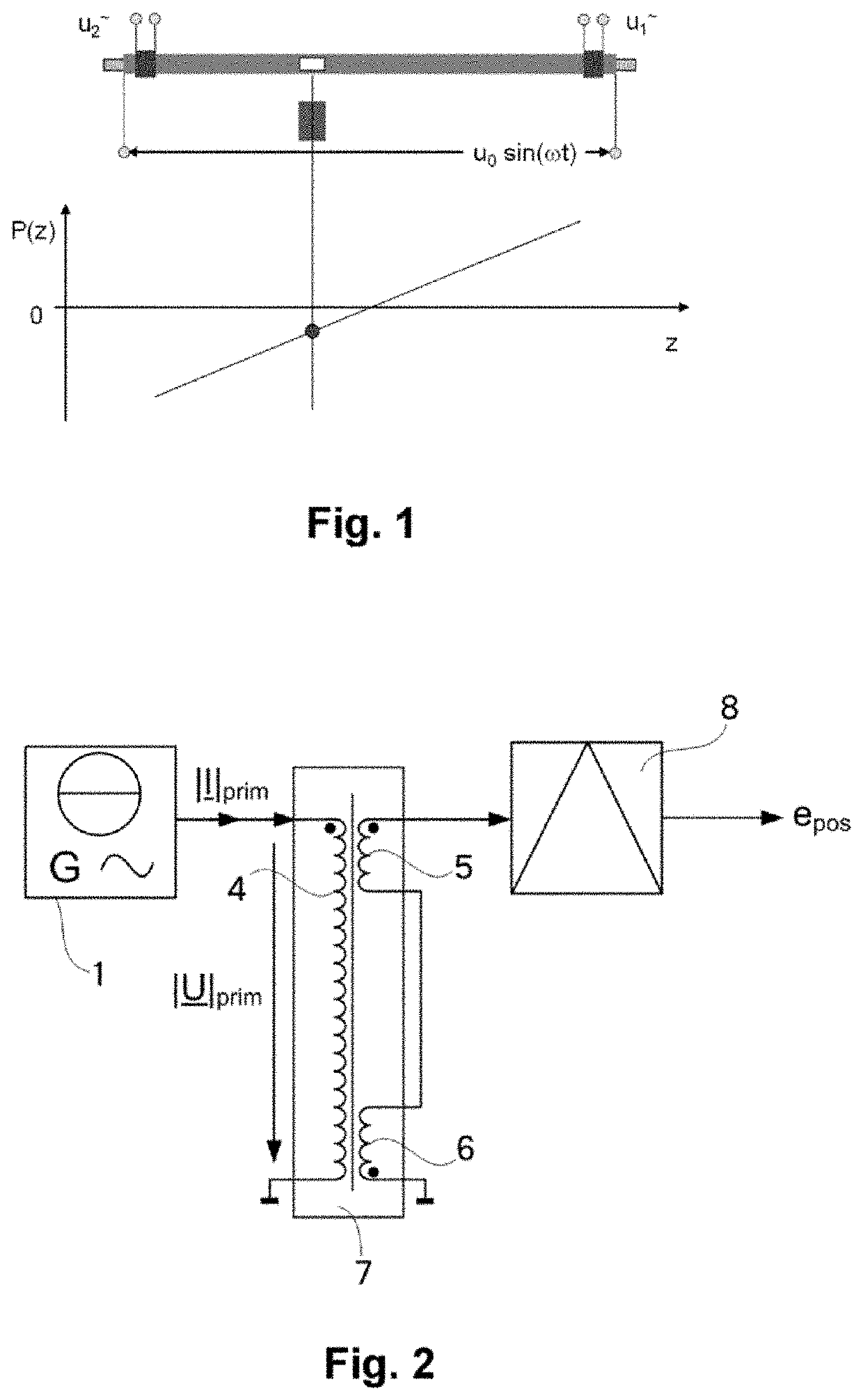
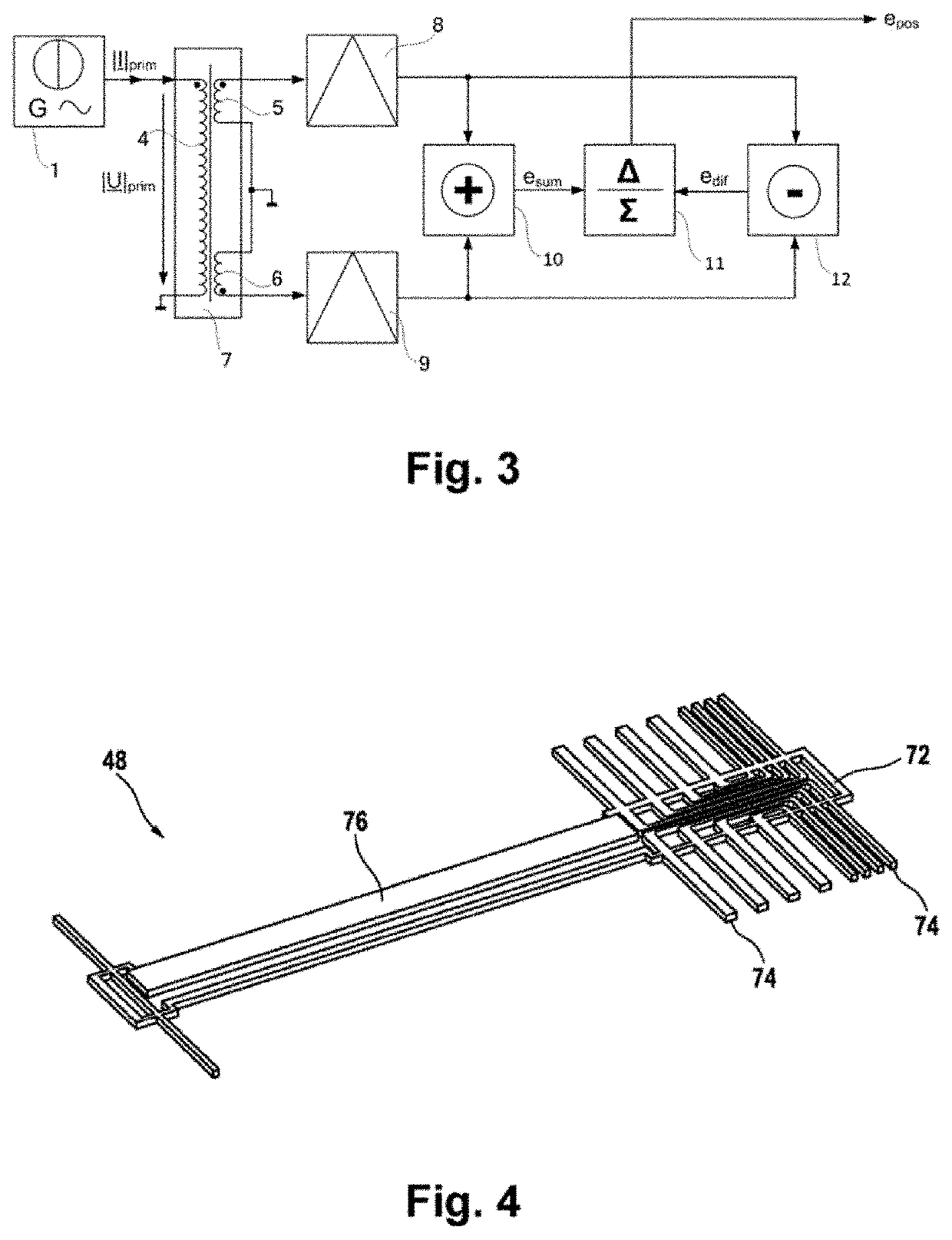
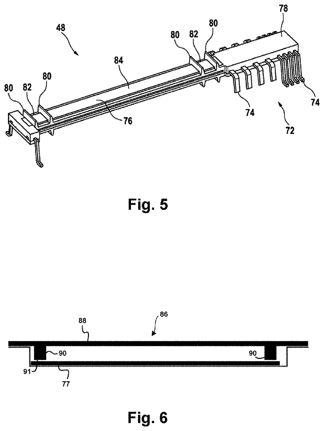
[0034]Reference is made to FIGS. 1-3, which show a displacement sensor by way of example in the form of a differential-transformer displacement sensor. The latter derives the measurement variable to be determined, the position of an encoder G, from the difference between two signals induced on the secondary side by an excitation coil 4. The excitation coil 4 and the receiving coils 5 and 6 therefore together form a transformer 7. If a permanent magnet is used as the encoder G, its magnetic field ensures a saturation zone in the soft-magnetic core material K of the functional core 76, said saturation zone for its part weighting the voltages induced on the secondary side proportionally in terms of the position. During normal operation, the permanent magnet which is used as the position encoder G therefore, depending on its position above the soft-magnetic functional core 76, changes the amplitude of the voltages induced in the receiving coils 5, 6. In this description, the term “recei...


PUM


Abstract

A displacement sensor for sensing a distance, including an excitation coil for exciting an electromagnetic alternating field, a receiver device for inductively receiving the electromagnetic alternating field and for outputting an output signal which is dependent on the received electromagnetic alternating field. The receiver device has a functional core which is surrounded by at least one receiving coil, and a return core. The return core is designed to shield the functional core from an external electromagnetic field, and the receiver device has a housing with a cavity in which the return core is arranged.

Description

CROSS REFERENCE TO RELATED APPLICATIONS[0001]This application is the U.S. National Phase Application of PCT International Application No. PCT / EP2019 / 073960, filed Sep. 9, 2019, which claims priority to German Patent Application No. 10 2018 217 517.9, filed Oct. 12, 2018, the contents of such applications being incorporated by reference herein.FIELD OF THE INVENTION[0002]The invention relates to a displacement sensor for sensing a distance, and to a method for producing same.BACKGROUND OF THE INVENTION[0003]DE 101 30 572 A1, incorporated herein by reference, discloses an inductive measuring transducer for a displacement sensor which, on the basis of a magnetic field of an encoder element, which is dependent on the position of the encoder element, outputs an electrical signal to an evaluation circuit.[0004]The requirements regarding the robustness of sensors against external magnetic fields have increased significantly in the recent past. In addition, however, the increasing cost pres...

Claims


Application Information

Patent Timeline
IPC IPC(8): G01D5/22
CPCG01D5/2291G01D5/2046G01D11/245G01D2205/40G01B7/00
Inventor GRUNWALD, FRANK
Owner CONTINENTAL TEVES AG & CO OHG
Why Eureka
Try Eureka