
Electrical machine, particularly a permanent magnet motor, and a method to provide the electrical windings thereof

a permanent magnet motor and electric machine technology, applied in the field of permanent magnet motors and electrical windings of electric machines, can solve problems such as wide overhang, and achieve the effects of avoiding disturbing impedance, facilitating identification of incoming signals, and low path distances

Active Publication Date: 2017-01-24
NIDEC MOTORS & ACTUATORS GERMANY
View PDF13 Cites 0 Cited by
  • Summary
  • Abstract
  • Description
  • Claims
  • Application Information

AI Technical Summary

Benefits of technology

This approach reduces the winding overhang height, simplifies wiring, and enhances production efficiency and product quality by maintaining electromagnetic design integrity while minimizing the number of connections, thus reducing rejection rates and improving manufacturing efficiency.

Problems solved by technology

Overall this results in an overhang that is wider, yet not as high.

Method used


Image

  • Electrical machine, particularly a permanent magnet motor, and a method to provide the electrical windings thereof
  • Electrical machine, particularly a permanent magnet motor, and a method to provide the electrical windings thereof
  • Electrical machine, particularly a permanent magnet motor, and a method to provide the electrical windings thereof

Examples


Embodiment Construction

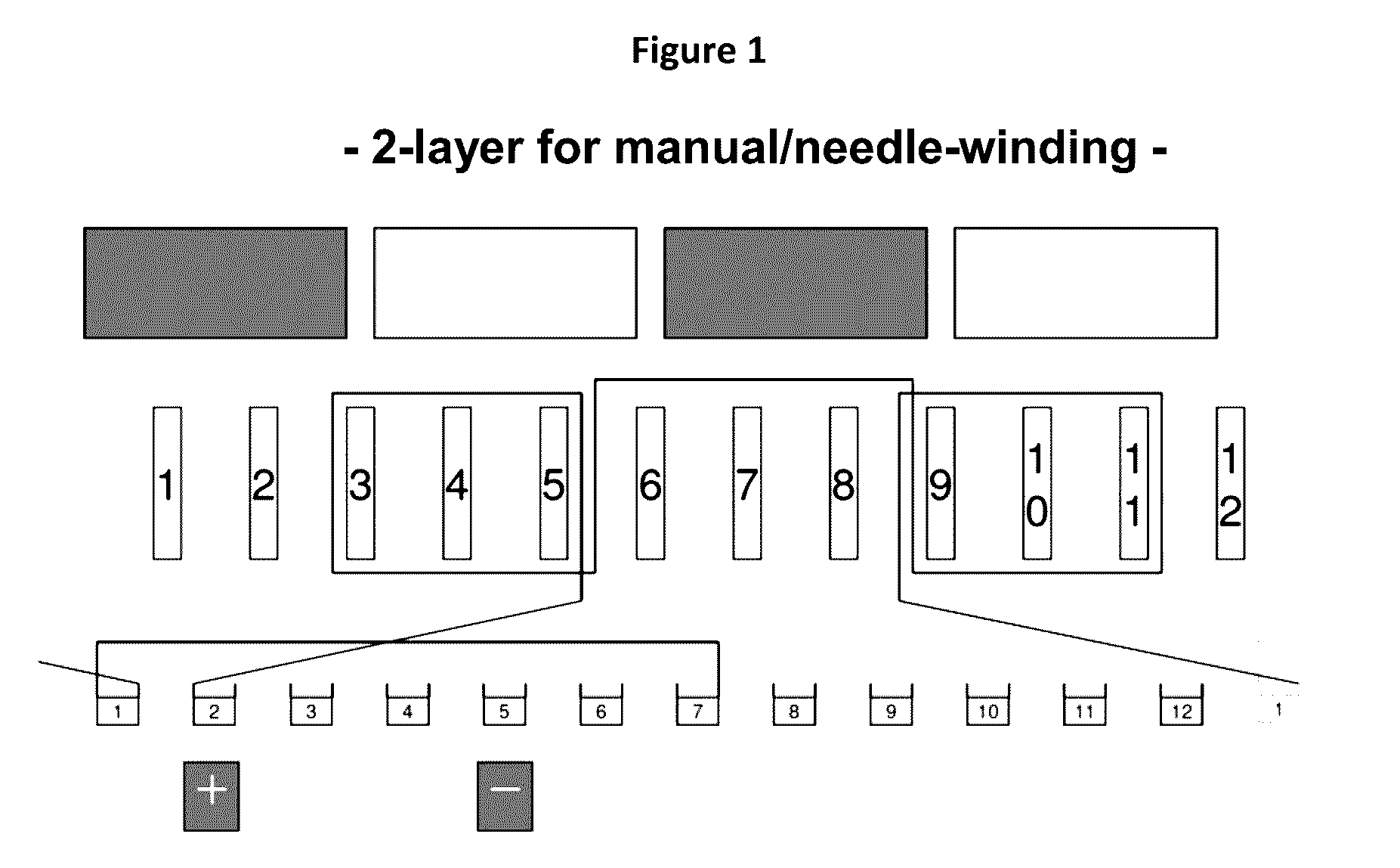
[0041]A first embodiment of the invention is described below with reference to FIG. 1. In particular, it relates to an electrical machine, namely a permanent magnet motor having a number of four magnetic poles where twelve teeth are arranged accordingly on the rotor, said teeth being arranged in four tooth or teeth groups consisting of three teeth each. The teeth are represented in the figure by rectangular boxes numbered 1 to 12.

[0042]Starting from the second commutator hook, the winding wire is lead to the gap between teeth 5 and 6 and, in the example shown, windings are provided in a clockwise direction around the tooth group consisting of teeth 3, 4 and 5 according to a predetermined number of coil-forming loops. In the present example, the number of coil-forming loops is determined to be half of the number of coil windings usually used to obtain the desired electromagnetic effect, where in the illustrated example, the wire diameter chosen corresponds to a traditional winding. O...


PUM

PropertyMeasurementUnit
diameteraaaaaaaaaa
rotational symmetryaaaaaaaaaa
angleaaaaaaaaaa

Abstract

An electrical machine, particularly a permanent magnet motor, having a number of poles and teeth or tooth groups that is divisible by a whole number A around which coil-forming loops of winding wire are arranged such that B coils are arranged in series, the coils having a number of windings equivalent to C / B where C is a whole number divisor of B and indicates the wire diameter as a quotient of a traditional standard winding, as well as a method to provide a corresponding winding structure.

Description

CROSS-REFERENCE TO RELATED APPLICATIONS[0001]The present application claims priority to and the benefit of the filing date of German Patent Application No. DE 10 2012 020 109.5 filed by the present inventors on Oct. 12, 2012.BACKGROUND OF THE INVENTION[0002]1. Field of the Invention[0003]The present invention concerns, in general, electrical machines, such as a permanent magnet motor, as well as a method for forming the windings contained therein.[0004]2. Brief Description of the Related Art[0005]Electrical machines are generally known and are used for various purposes and applications; they can, for example, be designed as ‘brush’ motors or ‘brushless’ motors, such as commonly used in motor vehicle applications, for example. For example, these types of motors include motors to adjust seats as well as drive motors used to rotate pumps or fan elements. Such electrical machines contain a stator and a rotor having magnetic poles. In this case, the stator is provided with windings, usua...

Claims


Application Information

Patent Timeline
Patent Type & Authority Patents(United States)
IPC IPC(8): H02K3/28H02K23/30H02K15/09H02K23/32H02K15/04
CPCH02K3/28H02K15/0442H02K15/09H02K23/30H02K23/32Y10T29/49071
Inventor SCHMID, JUERGENMEZGER, JUERGEN
Owner NIDEC MOTORS & ACTUATORS GERMANY
Learn More