Damping valve comprising a pressure relief valve

a technology of pressure relief valve and dripping valve, which is applied in the direction of functional valve types, shock absorbers, mechanical devices, etc., can solve the problem that the dripping orifice may not be sufficien

Inactive Publication Date: 2018-10-16
ZF FRIEDRICHSHAFEN AG
View PDF20 Cites 0 Cited by
  • Summary
  • Abstract
  • Description
  • Claims
  • Application Information

AI Technical Summary

Benefits of technology

[0007]In a preferred constructional variant, the pressure relief valve is connected in parallel with the choke orifice. The total flow quantity of damping medium and particularly the outflow cross section from the pressure space to the further space can be increased in this way.
[0011]A blocking or restriction of the pressure relief valve in the second direction is advantageous particularly when the pressure space forms a control space of the damping valve and accordingly, depending on the pressure inside the control space, influences a damping action in only one operating direction of the damping valve, for example, in push direction or in pull direction. In this way, the original damping characteristic of the damping valve is retained in the second direction. Further, the overpressure in the pressure space can be reduced in the first direction. Further explanations for reducing overpressure will be gathered from the description of the drawings.

Problems solved by technology

But during high loading of the damping valve, this choke orifice may not be sufficient for reducing an overpressure in the pressure space quickly enough.

Method used


Image

  • Damping valve comprising a pressure relief valve
  • Damping valve comprising a pressure relief valve
  • Damping valve comprising a pressure relief valve

Examples


Embodiment Construction

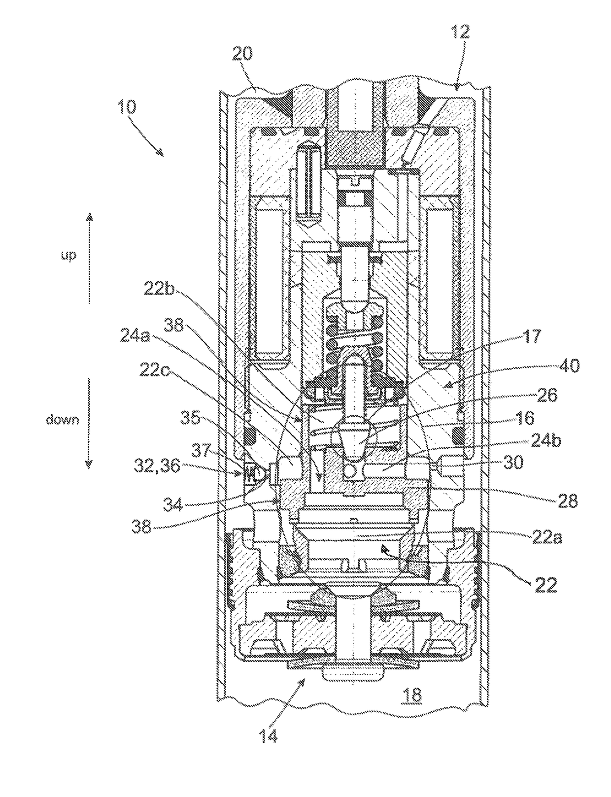
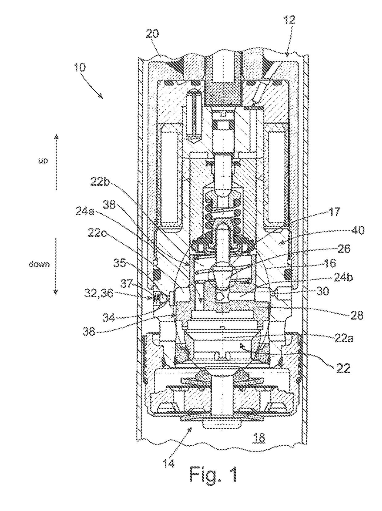
[0020]The directions “up” and “down” are shown in FIG. 1 and are used in the following for purposes of illustration.

[0021]FIG. 1 shows a cross section of a vibration damper 10 with an adjustable damping valve 12. The damping valve comprises an inlet valve 14, which is optional in this case, and an adjustable main valve 16 with a pre-valve 17. While the damping valve 12 separates a lower working space 18 from an upper working space 20, the main valve 16 divides the interior 22 into a plurality of partial spaces, including a main space 22a, a feed space 22b and a control space 22c. In the preceding as well as in the following, the control space 22c is also designated as pressure space 22c. The main space 22a and the feed space 22b are connected to one another via a channel 24a in a main valve body 28. Further, when a valve cone 26 of the pre-valve 17 lifts from the main valve body 28, a connection is made or blocked between the feed space 22b and the control space 22c via a further ch...


PUM


Abstract

An adjustable damping valve (12) includes a pressure space (22c) for controlling the damping valve (12), which pressure space (22c) is arranged inside the damping valve (12) and is connected to a further space (20) via at least one choke orifice (30) for the flow of damping medium, and the pressure space (22c) is operatively connected to the further space (20) via a pressure relief valve (32).

Description

PRIORITY CLAIM[0001]This is a U.S. national stage of application No. PCT / EP2015 / 065287, filed on Jul. 6, 2015. Priority is claimed on the following application(s): Country: Germany, Application No.: 10 2014 215 571.1, Filed: Aug. 6, 2014; the content of which is incorporated herein by reference in its entirety.FIELD OF THE INVENTION[0002]The invention is directed to a damping valve including a pressure relief valve and to a vibration damper with a damping valve of this type.BACKGROUND OF THE INVENTION[0003]A generic damping valve for a vibration damper is shown in DE 10 2009 059 808 A1. The damping valve forms an annular control space. This control space is operatively connected to an upper working space of the vibration damper via a choke orifice. Further, the control space is limited by a main stage body and valve housing. Main stage body and valve housing are aligned with one another via guide surfaces and can be displaced axially relative to one another. Further, the guide surfa...

Claims


Application Information

Patent Timeline
Patent Type & Authority Patents(United States)
IPC IPC(8): F16F9/34F16F9/46F16K17/04
CPCF16F9/34F16K17/0406F16F9/465
Inventor CALLIES, LOTHARSCHAFFELHOFER, TIMO
Owner ZF FRIEDRICHSHAFEN AG
Why Eureka
Try Eureka