Organic light-emitting device for lighting

a light-emitting device and organic technology, applied in the direction of organic semiconductor devices, light-emitting devices for light sources, light-emitting devices for heating apparatus, etc., can solve the problems of reducing the overall luminous efficiency of the oled, limiting the distance that light can travel forward, and lowering the light extraction efficiency. , to achieve the effect of increasing the light-emitting area, improving luminance, and increasing luminance efficiency

Active Publication Date: 2018-10-16
SAMSUNG CORNING PRECISION MATERIALS CO LTD
View PDF21 Cites 0 Cited by
  • Summary
  • Abstract
  • Description
  • Claims
  • Application Information

AI Technical Summary

Benefits of technology

[0022]According to the present disclosure, the flexible OLED configured such that at least one portion thereof has a curved surface is used as a light source. This can consequently increase the light-emitting area per the unit area of the OLED, thereby improving luminance.
[0023]In addition, according to the present disclosure, a reflector is disposed on an area except for an area through which light is emitted outwards. This can consequently increase luminance efficiency, thereby improving luminance.
[0024]Furthermore, according to the present disclosure, light-scattering particles are disposed in a filler layer. This can consequently increase the degree of scattering of light, thereby improving luminance.
[0025]In addition, according to the present disclosure, a transparent electrode is formed in place of an opaque metal electrode in order to realize a transparent flexible OLED. A plurality of transparent flexible OLEDs may be provided in order to further improve luminance.
[0026]Furthermore, according to the present disclosure, a light-scattering pattern may be formed on the inner and outer surfaces of the front substrate and the inner surface of the rear substrate in order to further improve luminance.
[0027]In addition, according to the present disclosure, a light extraction layer may be formed on the flexible OLED in order to improve the light extraction efficiency of the flexible OLED, thereby further improving the organic light-emitting device for lighting.

Problems solved by technology

This consequently lowers light extraction efficiency, thereby lowering the overall luminous efficiency of the OLED, which is problematic.
However, even if the above-described approaches have been introduced, the light-absorbing characteristics of materials of OLEDs limit distances that light can travel forwards.
Thus, light emitted by an OLED does not have sufficient opportunity to reach the light extraction layer that is disposed on the path along which the light is emitted outwards in order to improve light extraction efficiency.
It is highly probable that a current leakage may occur, which is problematic.

Method used


Image

  • Organic light-emitting device for lighting
  • Organic light-emitting device for lighting
  • Organic light-emitting device for lighting

Examples


first embodiment

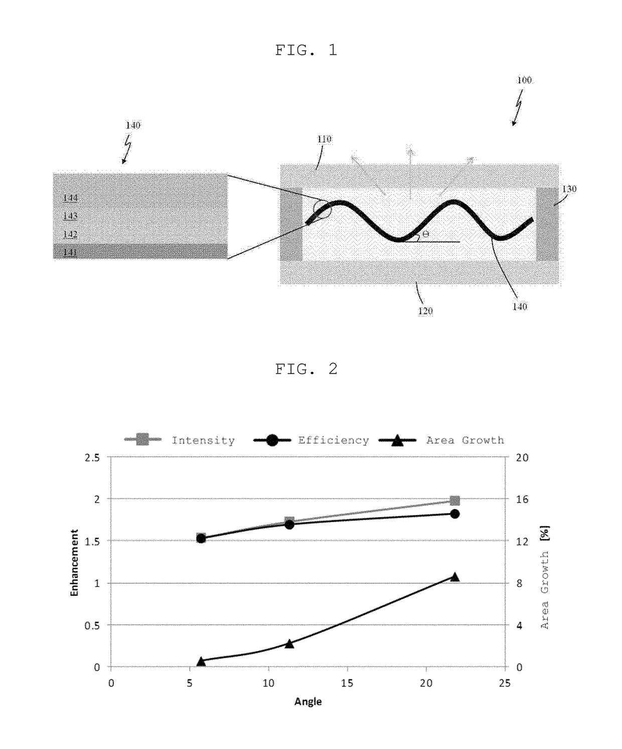
[0040]As illustrated in FIG. 1, an organic light-emitting device for lighting 100 includes a first substrate 110, a second substrate 120, a frame 130, and a flexible organic light-emitting diode (OLED) 140.

[0041]The first and second substrates 110 and 120 are disposed to face each other. In the first embodiment, light generated by the flexible OLED 140 is emitted outwards through the first substrate 110. In this regard, the first substrate 110 may be formed from a transparent plastic material or transparent glass. Here, the second substrate 120 may be formed from the same material as the first substrate 110.

[0042]The frame 130 is dispose between the first substrate 110 and the second substrate 120 that face each other. The frame 130 is formed along the peripheries of the first substrate 110 and the second substrate 120 to define a space between the first substrate 110 and the second substrate 120, i.e. a space in which the flexible OLED 140 is disposed, while hermetically sealing t...

second embodiment

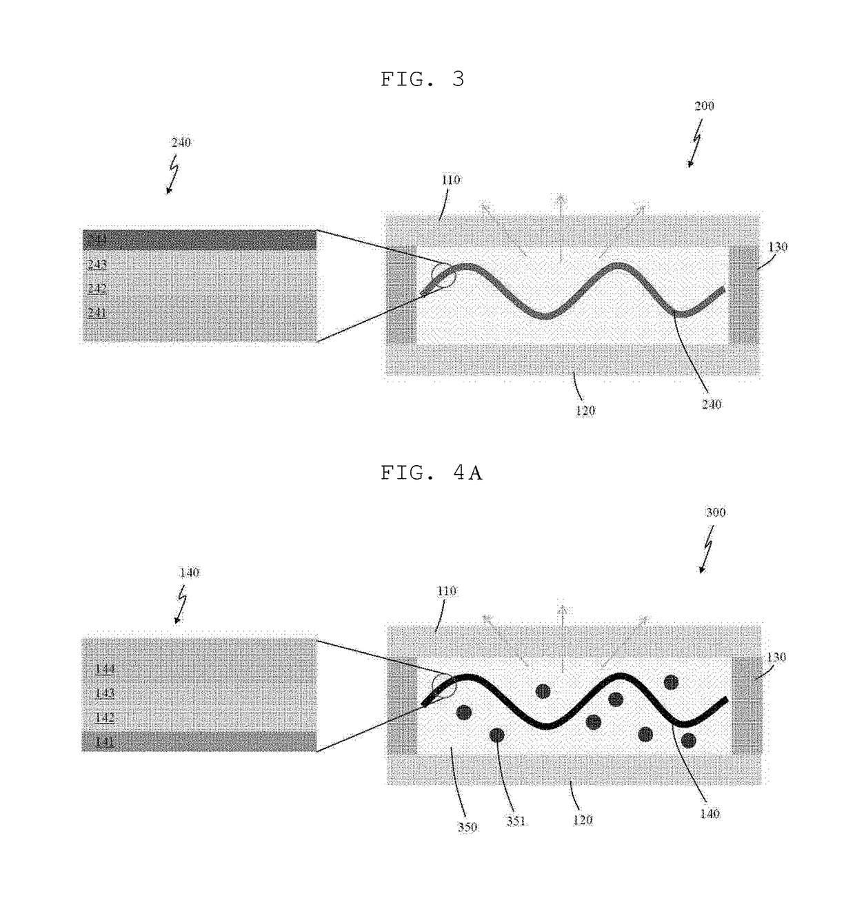
[0050]Hereinafter, reference will be made to an organic light-emitting device for lighting in conjunction with FIG. 3.

[0051]FIG. 3 is a cross-sectional view schematically illustrating the organic light-emitting device for lighting according to the second embodiment.

[0052]As illustrated in FIG. 3, the organic light-emitting device for lighting 200 according to the second embodiment includes a first substrate 110, a second substrate 120, a frame 130, and a flexible OLED 240.

[0053]The components of the second embodiment are substantially identical to those of the first embodiment except for the structure of the flexible OLED. The same reference numerals will be used to designate the same components, and descriptions thereof will be omitted.

[0054]The flexible OLED 240 according to the second embodiment is a transparent OLED having a double-sided light-emitting structure. In this regard, the flexible OLED 240 according to the second embodiment includes a flexible base 241 and a first tr...

third embodiment

[0056]Hereinafter, reference will be made to an organic light-emitting device for lighting in conjunction with FIG. 4.

[0057]FIG. 4 is a cross-sectional view schematically illustrating the organic light-emitting device for lighting according to the third embodiment.

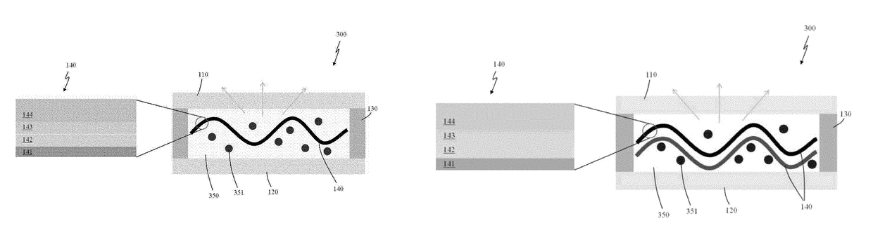
[0058]As illustrated in FIG. 4, the organic light-emitting device for lighting 300 according to the third embodiment includes a first substrate 110, a second substrate 120, a frame 130, a flexible OLED 140, and a filler layer 350.

[0059]The third embodiment is substantially identical to the first embodiment except for the filler layer being disposed in the space. The same reference numerals will be used to designate the same components, and descriptions thereof will be omitted.

[0060]The filler layer 350 is formed by filling the interior of the space defined by the first substrate 110, the second substrate 120, and the frame 130 with a resin material, such as PMA. The filler layer 350 serves to fix the flexible OLED 140, i....


PUM


Abstract

The present invention relates to an organic light-emitting device for lighting, and more specifically relates to an organic light-emitting device for lighting whereby it is possible to achieve excellent brightness by increasing the light-emitting area per unit area of an organic light-emitting element. For this purpose, the present invention provides an organic light-emitting device comprising: a first substrate and a second substrate disposed facing each other; a frame section which is formed between the first substrate and the second substrate, and is formed on the periphery of the first substrate and the second substrate so as to hermetically close the space between the first substrate and the second substrate; and a flexible organic light-emitting element which is disposed inside of the space, and of which at least one part has a curved surface.

Description

CROSS-REFERENCE TO RELATED APPLICATION[0001]This application is a national phase entry under 35 U.S.C. § 371 of International Application No. PCT / KR2014 / 011670, filed Dec. 2, 2014, published in Korean, which claims priority to Korean Patent Application No. 10-2013-0148298, filed on Dec. 2, 2013, the disclosures of which are incorporated herein by reference.TECHNICAL FIELD[0002]The present disclosure relates to an organic light-emitting device for lighting, and more particularly, to an organic light-emitting device for lighting in which superior luminance can be realized through increasing the light-emitting area per the unit area of an organic light-emitting diode (OLED).BACKGROUND ART[0003]Light-emitting devices may be generally divided into organic light-emitting devices in which a light-emitting layer is formed from an organic material and inorganic light-emitting devices in which a light-emitting layer is formed from an inorganic material. Organic light-emitting diodes (OLEDs), ...

Claims


Application Information

Patent Timeline
Patent Type & Authority Patents(United States)
IPC IPC(8): H01L29/08H01L51/52H01L51/50H01L51/00F21K9/68H04L29/04F21Y115/15H04L69/14
CPCF21K9/68H01L51/0097H01L51/5012H01L51/5221H01L51/5246H01L51/5271H01L51/5268Y02E10/549F21Y2115/15H01L51/5275H01L2251/5338H01L2251/5361H10K77/111H10K50/8426H10K50/854H10K50/858H10K50/84H10K50/85H10K50/856H10K50/11H10K50/82H10K2102/311
Inventor PARK, KYOUNG WOOKPARK, JUNE HYONGYOON, HONGKIM, SEO HYUNBAEK, IL HEEYOON, GUN SANGLEE, JOO YOUNGLEE, HYUN HEECHOI, EUN HO
Owner SAMSUNG CORNING PRECISION MATERIALS CO LTD
Why Eureka
Try Eureka