Respiratory humidifier

a respiratory humidifier and humidifier technology, applied in the field of respiratory humidifiers, can solve the problems of large corners and edges, large cost, and difficulty in adjusting settings, and achieve the effect of easy portability, long life and low cos

Active Publication Date: 2018-10-23
HAMILTON MEDICAL AG
View PDF6 Cites 2 Cited by
  • Summary
  • Abstract
  • Description
  • Claims
  • Application Information

AI Technical Summary

Benefits of technology

[0016]wherein the liquid container can be slid in such a way onto the housing to establish the operating state so that, when in operation, the projecting portion is positioned above the bottom plate. This design is relatively simple and compact and offers the user the ergonomically advantageous possibility of operating the respiratory humidifier and of inspecting its functional parameters both from above and from the front. Through the elimination of additional or complex elements, the respiratory humidifier is resistant to malfunction; and as a result of the simple sliding mechanism, operator errors are less likely to occur.
[0017]When the humidifier is in the operating state, the housing and the liquid container preferably form together an essentially continuous slanted top surface and an essentially continuous lateral surface of the respiratory humidifier, wherein the user interface is integrated into the slanted top surface. This makes the humidifier user-friendly, because, except for the connector elements, there are no large openings in the compact, easily stored unit.
[0018]It is especially advantageous for the housing to comprise first fastening means and for the liquid container to comprise second fastening means, wherein the sliding of the liquid container onto the housing brings about engagement between the first and the second fastening means in such a way that the bottom plate is pressed from above onto the heating plate. Because complete thermal and possibly also electrical contact between the heating plate and the bottom plate is essential to the proper functioning of the respiratory humidifier, the bottom plate must be pressed in some way onto the heating plate and held in that position. This is guaranteed by the engagement between the first and second fastening means. A fastening design of this type is simple and works without any complicated mechanisms on the heating plate such as those known from the prior art.
[0021]It is also advantageous for the engagement between the first and second fastening means to be established by a releasable latching mechanism. This latching mechanism is simple and works without any additional fasteners which would have to be operated by the user. It is thus a simple matter to replace the liquid container, which is usually designed as a single-use / disposable article.
[0023]It is advantageous for the at least one tongue to be designed as a one-piece spring plate element. Spring steel sheet material for spring plates is low in cost and easy to bring into the desired shape. In addition, it offers a solid and almost failure-proof spring function, which contributes to the long life of the respiratory humidifier.

Problems solved by technology

First is the stationary housing, which is connected to the power supply and possibly to other medical devices over a data line; second is the replaceable liquid container, which is usually delivered with the inhalation tubes already attached, so that there is as little chance as possible that the nursing personnel will connect them incorrectly.
In some cases, they are arranged underneath the liquid container, which means that it is awkward to access them to read or adjust the settings.
Another disadvantage of the known respiratory humidifiers is that they are relatively large and awkwardly shaped with many corners and edges, for example.
They also comprise a large number of connections and contain complicated structural elements.
Such devices are therefore complicated to operate, subject to malfunction, and expensive to acquire.

Method used


Image

  • Respiratory humidifier
  • Respiratory humidifier
  • Respiratory humidifier

Examples


Embodiment Construction

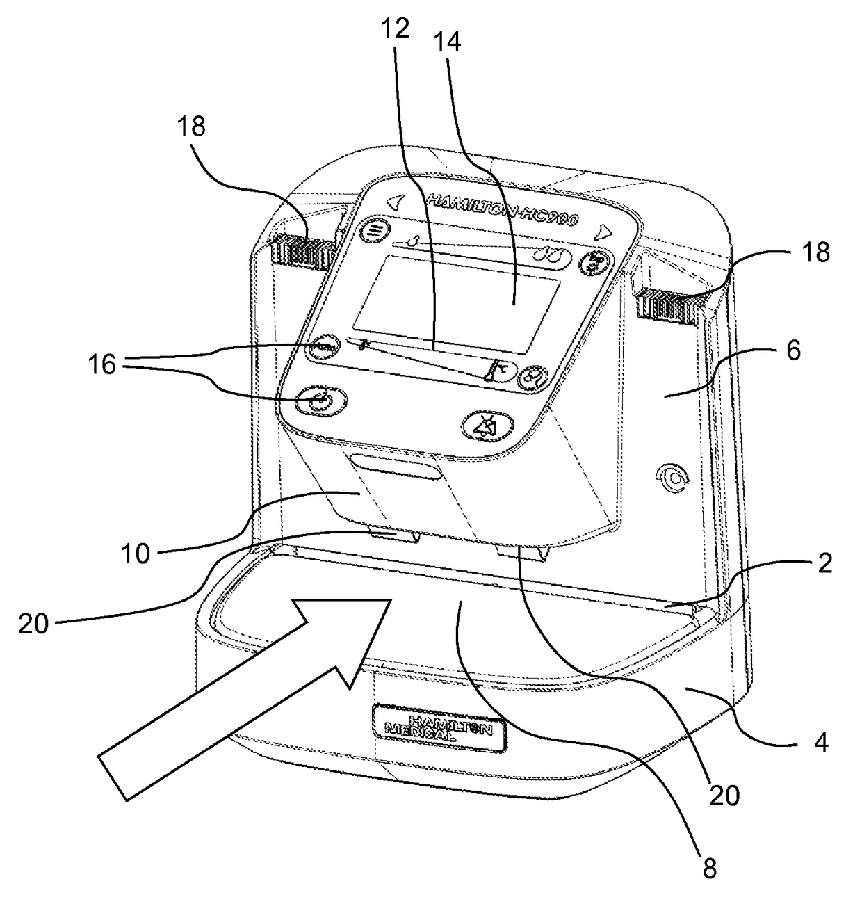
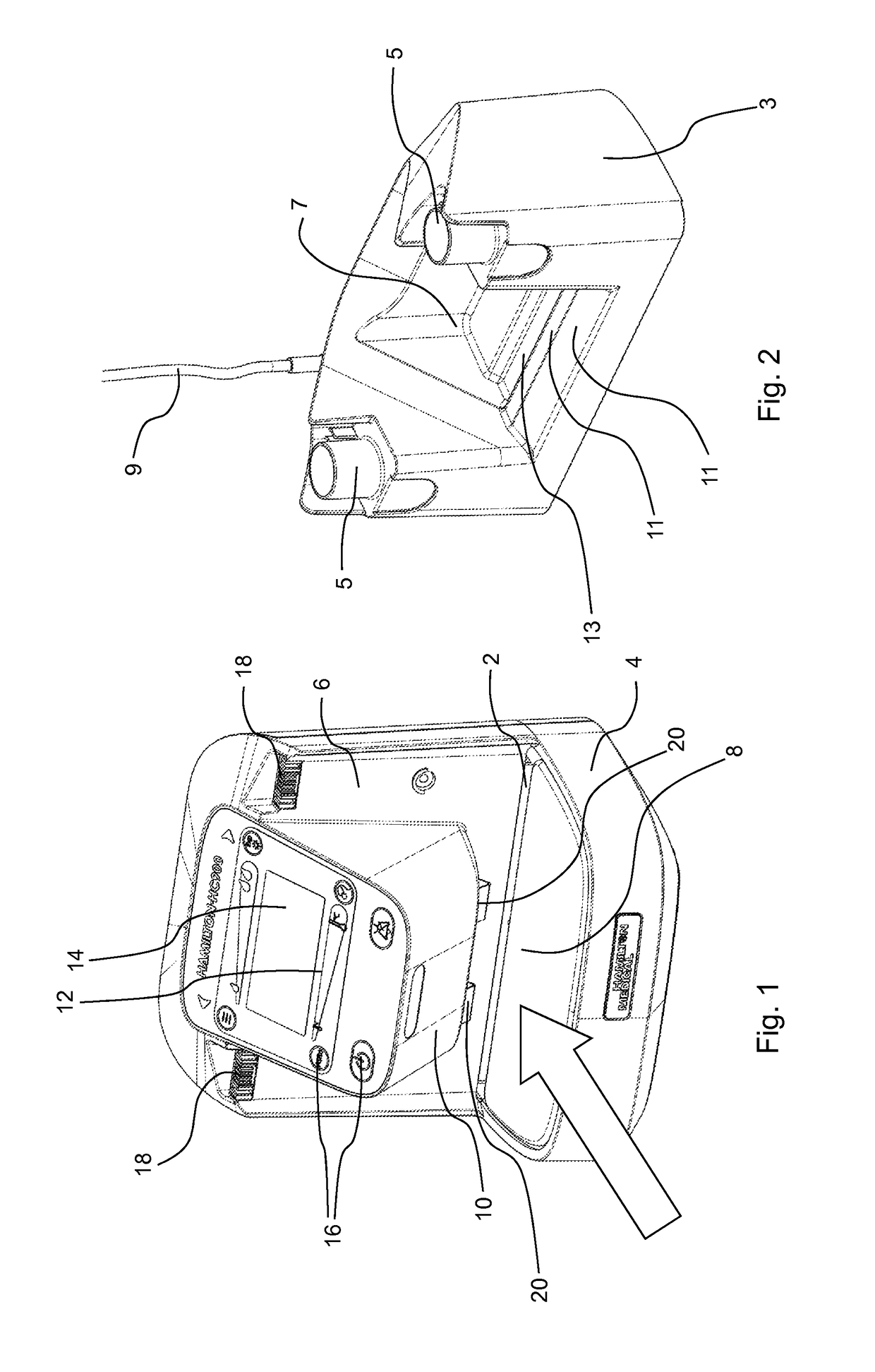
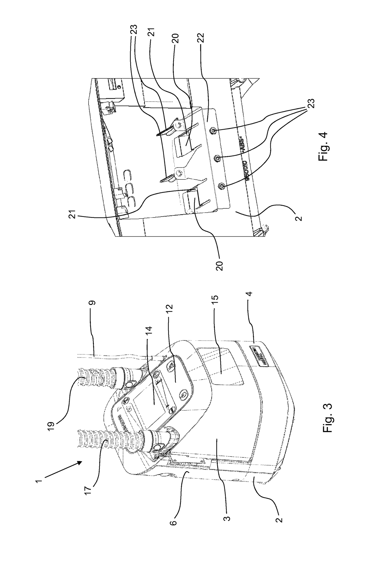
[0033]FIG. 1 shows a perspective view of the housing 2 of a preferred embodiment of the respiratory humidifier according to the invention. The housing 2 comprises essentially an L-shape with a horizontal part 4 and a vertical part 6. On the horizontal part 4, a heating plate 8 is arranged, which is oriented essentially horizontally and which covers almost the entire upward-facing surface of the horizontal part 4. A projecting portion 10 extends from approximately the middle of the upper, free end of the vertical part 6, wherein the surface of the projecting portion 10 comprises a user interface 12. The user interface 12 comprises a display device 14 and operating elements 16, by means of which the respiratory humidifier can be monitored and controlled. Electrical contact elements 18 are arranged at the upper end of the vertical part 6, offset laterally from the projecting portion 10; these elements can be brought into electrical contact with corresponding connecting parts of a venti...


PUM


Abstract

A respiratory humidifier (1) for a ventilation system is provided, the humidifier comprising:a housing (2), which is designed essentially in the shape of an “L” with a horizontal and a vertical part (4, 6) and a projecting portion (10) extending from the free end of the vertical part (6) toward the horizontal part (4), and which comprises a control unit, a user interface (12), and a heating plate (8), wherein the user interface (12) is arranged on the projecting portion (10) and the heating plate (8) is arranged on the horizontal part (4); anda liquid container (3), which is designed essentially in the shape of a “U”, comprising a recess (7) and a bottom plate (24) as well as two connector elements (5), each of which establishes a connection with a breathing tube;wherein the heating plate (8) can be heated for heating the liquid in the liquid container (3), and the bottom plate (24) can be brought into contact with the heating plate (8);wherein the liquid container (3) can be slid in such a way onto the housing (2) to establish an operating state so that, when in said operating state, the projecting portion (10) of the housing (2) is positioned above the bottom plate (24) of the liquid container (3).

Description

FIELD OF THE INVENTION[0001]The present invention pertains to a respiratory humidifier or respiratory humidifier for a ventilation system.BACKGROUND OF THE INVENTION[0002]When patients are being mechanically ventilated on an intensive-care ward, for example, the patient to be ventilated is connected pneumatically to the ventilator or respirator by a system of ventilation tubing. Because the breathing air delivered to the patient must be adjusted with respect to temperature and humidity to meet the physiological needs of the patient, a respiratory humidifier or respiratory humidifier is arranged in the inhalation or inspiration tube to heat and humidify the breathing air. The respiratory humidifier comprises a liquid container filled with distilled water, through which the breathing air is conducted and humidified.[0003]The heating of the liquid in the liquid container is usually accomplished by means of a heating plate in the bottom part of the housing of the respiratory humidifier,...

Claims


Application Information

Patent Timeline
Patent Type & Authority Patents(United States)
IPC IPC(8): A61M16/10A61M16/00A61M11/04A61M16/16
CPCA61M16/109A61M11/042A61M16/16A61M16/0003A61M2209/086A61M2205/502
Inventor BUECHI, RUDOLF
Owner HAMILTON MEDICAL AG
Why Eureka
Try Eureka