U-bend pipe type heat exchanger

a heat exchanger and u-bend technology, applied in indirect heat exchangers, air heaters, light and heating equipment, etc., can solve the problems of water jacket type heat exchanger not meeting high-level pressure-resistance test criteria, increased overall size of heat exchangers, and reduced thermal efficiency, so as to achieve the effect of high pressure-resistance and minimize the use of water jackets

Active Publication Date: 2018-10-23
KITURAMI BOILER
View PDF12 Cites 2 Cited by
  • Summary
  • Abstract
  • Description
  • Claims
  • Application Information

AI Technical Summary

Benefits of technology

[0009]Some embodiments of the present disclosure provide a U-bend pipe type heat exchanger which prevents U-shaped pipes from being exposed outside of a main body of the heat exchanger and minimizes a use of water jackets, thereby reducing an overall size of the heat exchanger, suppressing heat loss, and achieving a high pressure-resistance.
[0017]Therefore, the use of water jackets can be minimized while preventing the U-shaped pipes from being exposed outside. Further, it is possible to provide a high pressure-resistance while suppressing an increase in overall size of a heat exchanger and heat loss.

Problems solved by technology

However, in the U-shaped pipe type heat exchanger, the heat exchanger increases in overall size thereof because the U-shaped pipes protrude outward from the main body.
Further, thermal efficiency is lowered because heat dissipation in the U-shaped pipes exposed outside generates heat loss.
However, the water jacket type heat exchanger does not satisfy high-level pressure-resistance test criteria.
That is to say, in the water jacket type heat exchanger, deformation by pressure or damage may occur due to expansion of side surfaces of the heat exchanger by pressure or insufficient uniformity in brazing during a manufacturing process.

Method used


Image

  • U-bend pipe type heat exchanger
  • U-bend pipe type heat exchanger
  • U-bend pipe type heat exchanger

Examples


Embodiment Construction

[0026]Hereinafter, a U-bend pipe type heat exchanger according to an embodiment of the present disclosure will be described in detail with reference to the accompanying drawings.

[0027]In the following description, a side where a burner is installed and an opposite side thereto are defined as an “upper side” and a “lower side,” respectively. However, it would be obvious that definition of the upper and lower sides may be reversed according to an installation position of the burner.

[0028]In addition, in the following description, a main body of a heat exchanger is divided into front, back, left, and right side plates. However, it would be obvious that forward, backward, leftward, and rightward directions may be varied depending on a viewpoint.

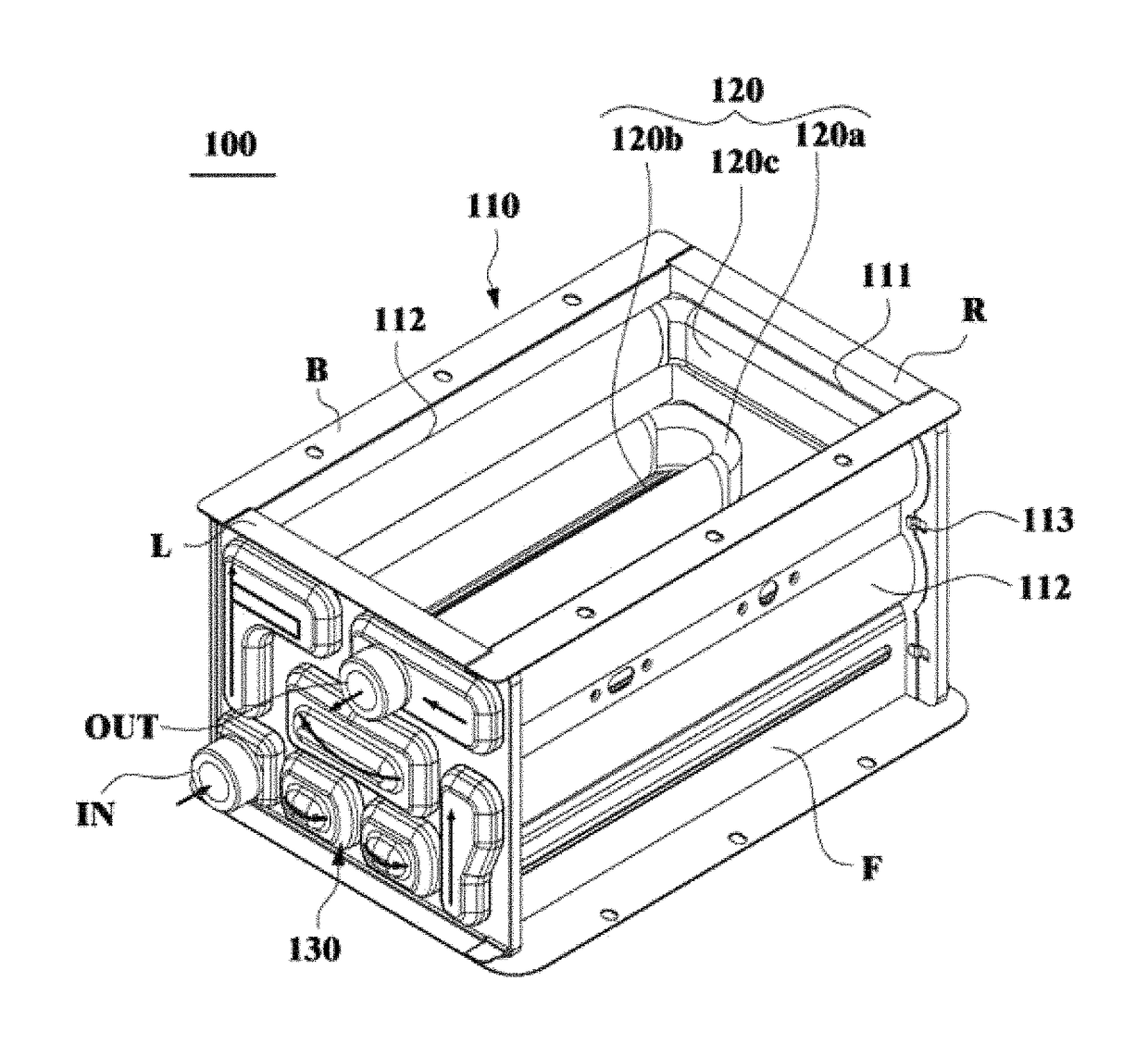
[0029]FIG. 3 illustrates a perspective view of a U-bend pipe type heat exchanger according to an embodiment of the present disclosure. FIG. 4 illustrates another perspective view of the U-bend pipe type heat exchanger according to the embodiment ...


PUM


Abstract

A U-bend pipe type heat exchanger includes: a heat exchanger main body surrounded by a front side plate, a back side plate, a left side plate, and a right side plate, and having open upper and lower portions through which a heat source passes; a plurality of U-bend pipes inserted between the left side plate and the right side plate, each of the plurality of U-bend pipes including two heat exchange pipes arranged in parallel with each other and a U-shaped pipe connecting one end portions of the two heat exchange pipes; and a plurality of water jackets attached to at least one of outward surfaces of the left side plate and the right side plate, and connecting open end portions of two adjacent heat exchange pipes such that a low-temperature water circulates along the plurality of U-bend pipes.

Description

CROSS REFERENCE[0001]This application claims the benefit of Patent Application No. 10-2016-0054463, filed on May 3, 2016 with Korean Patent Office, the disclosure of which is incorporated herein its entirety by reference.BACKGROUND[0002]The present disclosure relates to a U-bend pipe type heat exchanger, and, more particularly, to a U-bend pipe type heat exchanger which includes a heat exchanger main body having a plurality of U-bend pipes, each of which is configured by integrating heat exchange pipes and a U-shaped pipe, and performs heat exchange between a low-temperature water and a heat source.[0003]A heat exchanger crosses a heating fluid and a heating target fluid differing in temperature from each other to allow heat delivery therebetween, and is used to heat a low-temperature water circulating in a boiler or a water heater to supply a hot water or a heating water.[0004]In the heat exchanger, a plurality of heat exchange pipes installed in a main body of the heat exchanger i...

Claims


Application Information

Patent Timeline
Patent Type & Authority Patents(United States)
IPC IPC(8): F28F9/013F28D1/04F28F13/06F28D21/00F24H8/00F28D1/03F28D7/16
CPCF28F9/0131F24H8/00F28D1/0358F28D1/0443Y02B30/102F28D7/1623F28D21/0007F28F13/06F28F2270/02F28D7/163F28D7/14F28D7/06F28D2021/0024F28F9/001F28F9/02F28F9/26Y02B30/00F24H1/40F28D1/0213F28D1/047F24H1/38F28D1/0476
Inventor CHOI, SUNG-HWANSHIN, YOUN-CHEOLKIM, TAE-YOUNGJEON, YOUNG-HYOJUNG, HAE-YOUNG
Owner KITURAMI BOILER
Why Eureka
Try Eureka