
Proximity sensor and mobile device using the same

a proximity sensor and mobile device technology, applied in the field of sensors, can solve the problems of not appealing to the market and reducing the sensitivity of the proximity sensor, and achieve the effect of improving sensitivity

Active Publication Date: 2018-10-23
LITE ON SINGAPORE PTE LTD
View PDF18 Cites 1 Cited by
  • Summary
  • Abstract
  • Description
  • Claims
  • Application Information

AI Technical Summary

Benefits of technology

The patent aims to improve the sensitivity of a mobile device's proximity sensor. By making the emitter package taller and placing the emitter between the first and second geometric centerlines, the sensor has less crosstalk and achieves better accuracy. This results in a more accurate detection of objects near the mobile device.

Problems solved by technology

However, the above structure in the prior art takes up much inner space of the mobile device, which does not appeal to the market.
Furthermore, the miniaturization of the opening for the proximity sensor on the mobile phone casing and the combination of the emitter opening with the detector opening are also demanded by the market, which brings the challenge of reducing the distance between the emitter and the detector while at the same time maintaining the size of the detector opening.
However, with the emitter and the detector being brought closer to one another, the crosstalk level will increase, thus decreasing the sensitivity of the proximity sensor.

Method used


Image

  • Proximity sensor and mobile device using the same
  • Proximity sensor and mobile device using the same
  • Proximity sensor and mobile device using the same

Examples


Embodiment Construction

[0014]The aforementioned illustrations and following detailed description are exemplary for the purpose of further explaining the scope of the present disclosure. Other objectives and advantages related to the present disclosure will be illustrated in the following description and appended drawings.

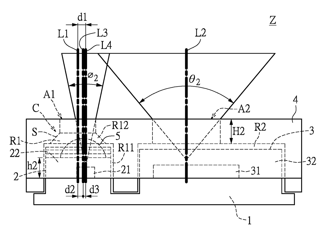
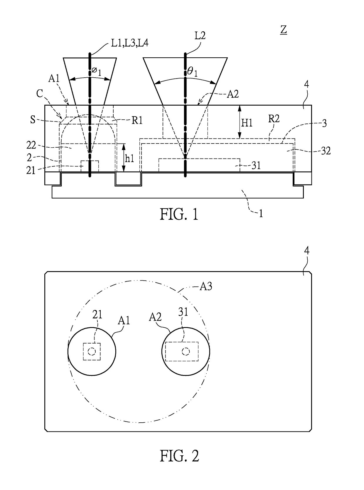
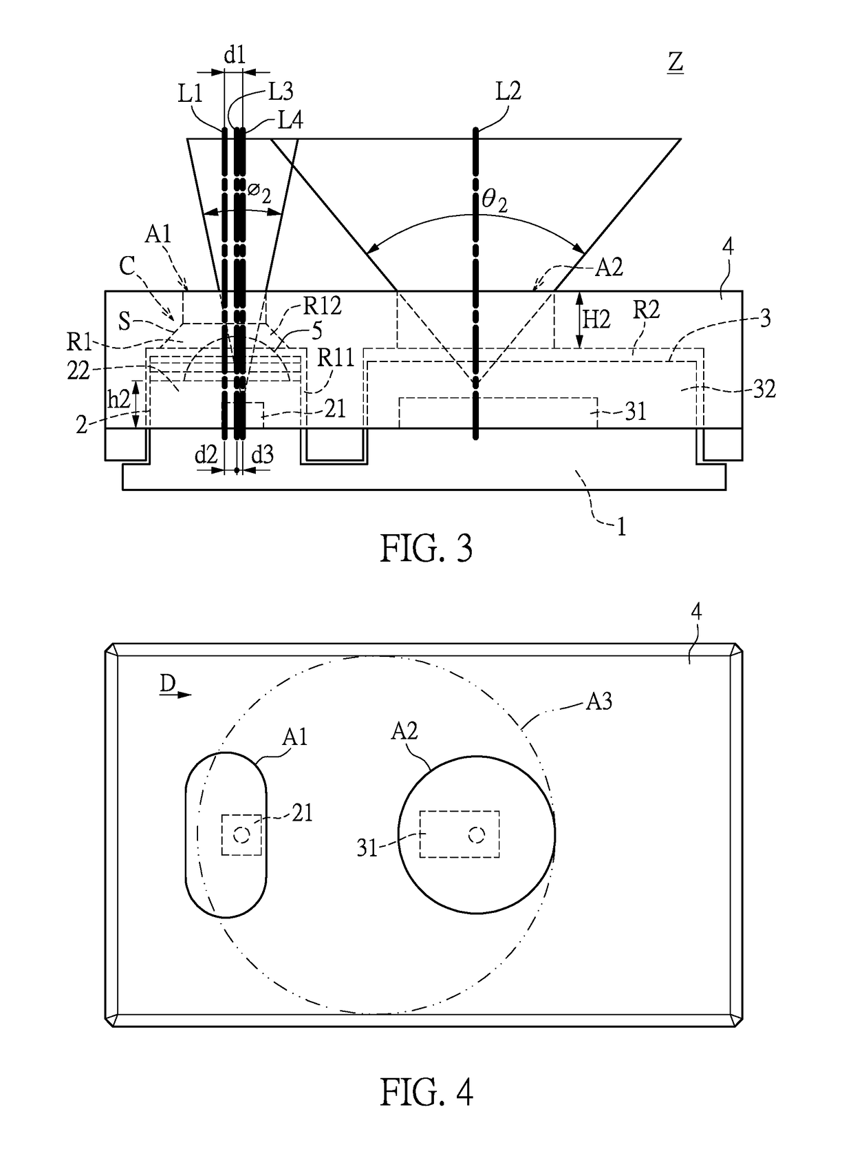
[0015]Referring to FIGS. 1 and 2, the present disclosure provides a proximity sensor Z including a circuit board 1, an emitter package 2, a receiver package 3, a plastic casing 4, and a lens 5. The emitter package 2 is disposed on the circuit board 1 and includes an emitter 21 and an emitter housing 22. In the present embodiment, the emitter 21 is an infrared light emitting diode (IR LED); however, the present disclosure is not limited thereto. The receiver package 3 is disposed on the circuit board 1 and includes a receiver 31 and a receiver housing 32.

[0016]Furthermore, the plastic casing 4 covers the emitter package 2 and the receiver package 3, in which the plastic casing 4 includes a...


PUM


Abstract

A proximity sensor and a mobile device using the same are provided. The proximity sensor includes a circuit board, an emitter package, a receiver package, a plastic casing and a lens. The emitter package is disposed on the circuit board and includes an emitter and an emitter housing. The receiver package is disposed on the circuit board and includes a receiver and a receiver housing. The plastic casing covers the emitter package and the receiver package. The plastic casing includes a first opening corresponding to the emitter package and a second opening corresponding to the receiver package. The first opening has a first geometric centerline and the second opening has a second geometric centerline. The height of the emitter package is smaller than that of the receiver package, and the emitter is disposed between the first geometric centerline and the second geometric centerline.

Description

BACKGROUND OF THE INVENTION1. Field of the Invention[0001]The present disclosure relates to a sensor; more particularly, to a proximity sensor and a mobile device using the same.2. Description of Related Art[0002]As technology advances, mobile devices with a touch screen have become increasingly popular, leading to a rising demand for a built-in proximity sensor. A proximity sensor serves to sense the face, ear and hair of a user when the user is having a phone call, and temporarily turns off the touch control function so as to save power on the one hand and prevent inadvertent touch inputs on the other.[0003]The emitter and the detector of a prior art proximity sensor are disposed separate from each other on the inner side of the touch screen, and an infrared shielding separator is disposed between the emitter and the detector to reduce crosstalk. However, the above structure in the prior art takes up much inner space of the mobile device, which does not appeal to the market. There...

Claims


Application Information

Patent Timeline
Patent Type & Authority Patents(United States)
IPC IPC(8): G01J5/00H05K1/18H01L25/16H01L31/16G01S17/02G01S7/481H01L31/0232G06F1/32G01S17/04
CPCG01S17/026H05K1/181H01L25/165H01L31/16H01L25/167G01S7/4813H01L31/02327G06F1/3231H05K2201/10121H05K2201/10106H05K2201/10151G06F3/0428H01L33/58H05K1/18G06F1/1626G06F1/169G06F1/1684G06F1/3262G06F1/3215G01S17/04Y02D10/00G06F3/041
Inventor GOH, TECK-CHAILIM, SIN-HENGSONG, GUANG-LIGOPALASWAMY, ARAKCRE DINESH
Owner LITE ON SINGAPORE PTE LTD
Learn More