Systems and methods for UV-based suppression of plasma instability

a plasma instability and plasma technology, applied in the direction of coatings, chemical vapor deposition coatings, electric discharge tubes, etc., can solve the problems of non-uniform processing results on the substrate, not providing adequate control of all plasma characteristics and behavior,

Active Publication Date: 2018-10-23
LAM RES CORP
View PDF1 Cites 0 Cited by
  • Summary
  • Abstract
  • Description
  • Claims
  • Application Information

AI Technical Summary

Problems solved by technology

However, in some plasma processes, the above-mentioned process parameters may not provide for adequate control of all plasma characteristics and behavior.
The formation of plasmoids can lead to non-uniformity in the processing results on the substrate.

Method used


Image

  • Systems and methods for UV-based suppression of plasma instability
  • Systems and methods for UV-based suppression of plasma instability
  • Systems and methods for UV-based suppression of plasma instability

Examples


Embodiment Construction

[0024]In the following description, numerous specific details are set forth in order to provide a thorough understanding of the present invention. It will be apparent, however, to one skilled in the art that the present invention may be practiced without some or all of these specific details. In other instances, well known process operations have not been described in detail in order not to unnecessarily obscure the present invention.

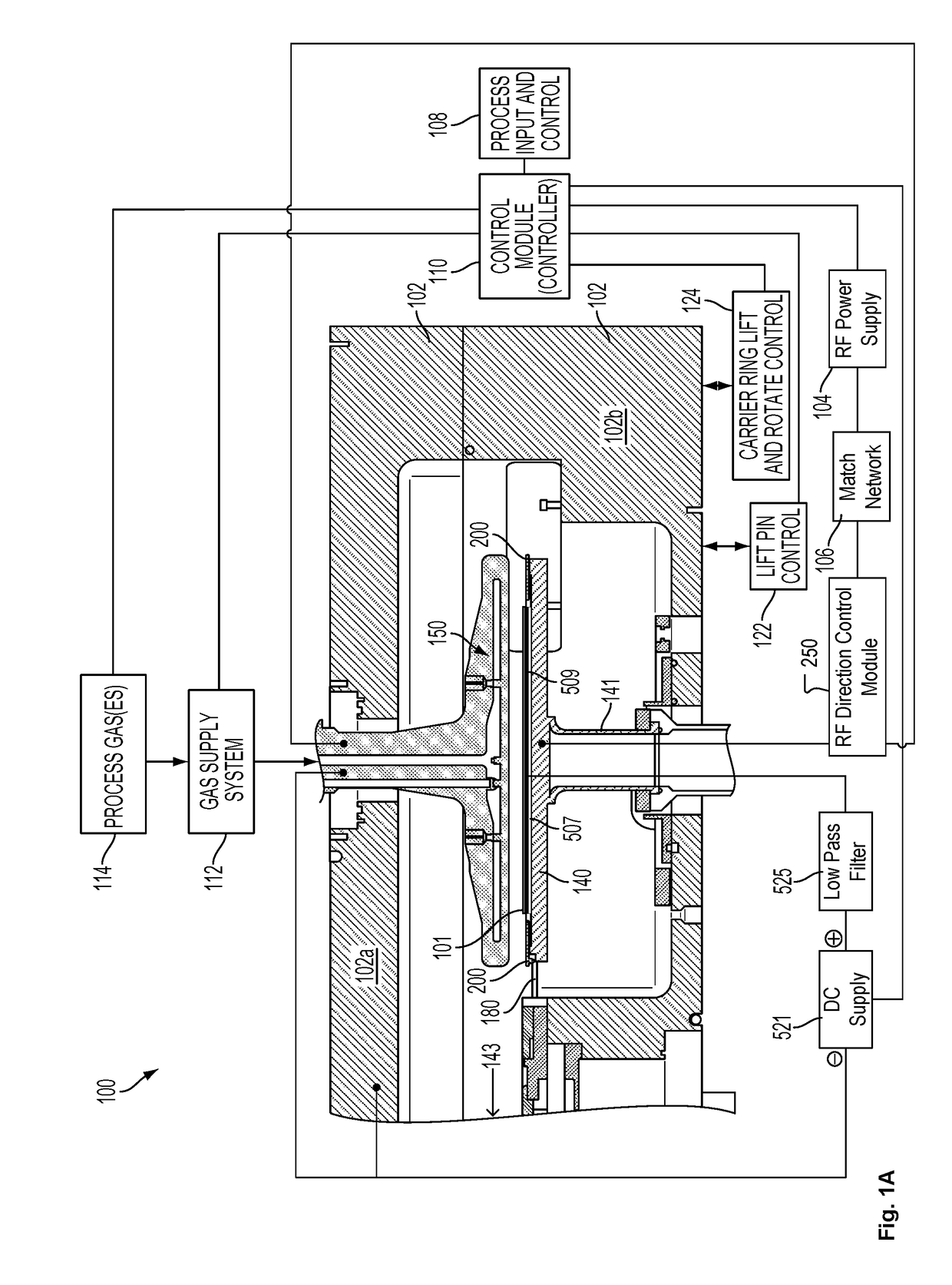
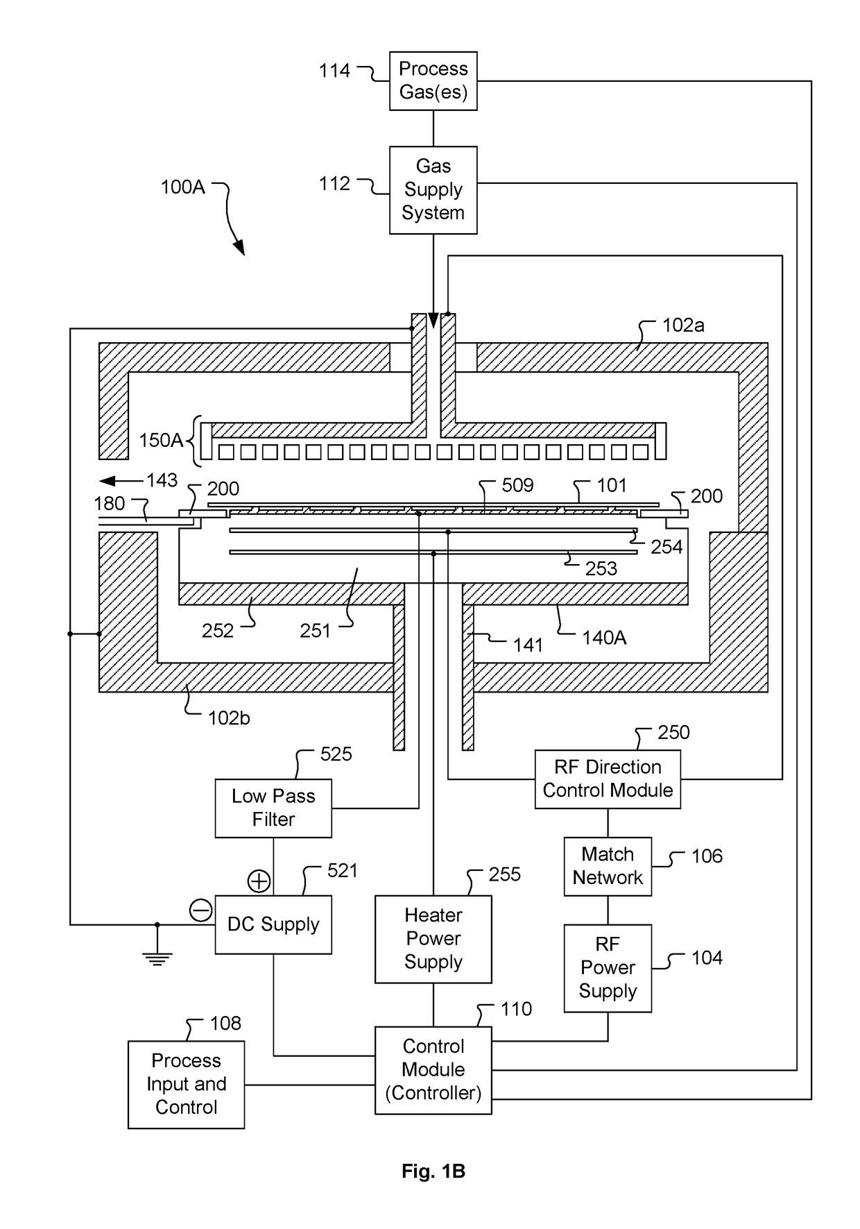
[0025]Deposition of films can be implemented in a plasma enhanced chemical vapor deposition (PECVD) system. The PECVD system may take many different forms. The PECVD system includes one or more chambers or “reactors” (sometimes including multiple stations) that house one or more substrates and are suitable for substrate processing. Each chamber may house one or more substrates for processing. The one or more chambers maintain the substrate in a defined position or positions (with or without motion within that position, e.g. rotation, vibration, or other...


PUM

PropertyMeasurementUnit
thicknessaaaaaaaaaa
thicknessaaaaaaaaaa
frequenciesaaaaaaaaaa

Abstract

A substrate is positioned in exposure to a plasma generation region within a plasma processing chamber. A first plasma is generated within the plasma generation region. The first plasma is configured to cause deposition of a film on the substrate until the film deposited on the substrate reaches a threshold film thickness. The substrate is then exposed to ultraviolet radiation to resolve defects within the film deposited on the substrate. The ultraviolet radiation can be supplied in-situ using either a second plasma configured to generate ultraviolet radiation or an ultraviolet irradiation device disposed in exposure to the plasma generation region. The ultraviolet radiation can also be supplied ex-situ by moving the substrate to an ultraviolet irradiation device separate from the plasma processing chamber. The substrate can be exposed to the ultraviolet radiation in a repeated manner to resolve defects within the deposited film as the film thickness increases.

Description

BACKGROUND[0001]1. Field of the Invention[0002]The present invention relates to semiconductor device fabrication.[0003]2. Description of the Related Art[0004]Many modern semiconductor chip fabrication processes include generation of a plasma from which ions and / or radical constituents are derived for use in either directly or indirectly affecting a change on a surface of a substrate exposed to the plasma. For example, various plasma-based processes can be used to etch material from a substrate surface, deposit material onto a substrate surface, or modify a material already present on a substrate surface. The plasma is often generated by applying radiofrequency (RF) power to a process gas in a controlled environment, such that the process gas becomes energized and transforms into the desired plasma. The characteristics of the plasma are affected by many process parameters including, but not limited to, material composition of the process gas, flow rate of the process gas, geometric f...

Claims


Application Information

Patent Timeline
Patent Type & Authority Patents(United States)
IPC IPC(8): H01L21/02C23C16/40C23C16/505C23C16/56C23C16/509
CPCH01L21/02348C23C16/402C23C16/505H01L21/02274C23C16/56H01L21/02164C23C16/5096H01L21/48H01L21/0228C23C16/509C23C16/482H01J37/32174H01J37/3244H01L21/0231C23C16/45536
Inventor SWAMINATHAN, SHANKAR
Owner LAM RES CORP
Why Eureka
Try Eureka