
Thermally stable monolith catalyst for reforming reaction

a monolith catalyst, thermal stability technology, applied in the direction of physical/chemical process catalysts, metal/metal-oxide/metal-hydroxide catalysts, sustainable manufacturing/processing, etc., can solve the problem of increasing the burden on the industry, deteriorating the catalytic activity, and reducing the activation point, so as to reduce the amount of catalyst used.

Active Publication Date: 2018-10-30
KOREA RES INST OF CHEM TECH
View PDF15 Cites 1 Cited by
  • Summary
  • Abstract
  • Description
  • Claims
  • Application Information

AI Technical Summary

Benefits of technology

The invention aims to solve problems with traditional monolith catalysts used for reforming reactions. These catalysts often lose their effectiveness due to carbon deposition and degradation during use. The invention introduces a new monolith catalyst that prevents this degradation by using a proper amount of certain metal barrier components. These metals prevent the growth of active particles, resulting in a more stable and effective catalyst. The new catalyst also reduces the amount of catalyst needed and has improved activity compared to existing monolith catalysts.

Problems solved by technology

Among those, the Korean Government has established the goal of 37% decrease in greenhouse gas, compared to the estimated exhaust for 2030, thus increasing a burden on the industry.
Such a carbon dioxide reforming reaction is a strong endothermic reaction wherein a theoretical maximum conversion rate at a predetermined temperature, that is, an equilibrium conversion rate is increased at a higher temperature, and thus the reaction occurs at a temperature of 650° C. or more, and is generally progressing at a high temperature of 850° C. However, the reaction at the high temperature described above enables catalyst particles to be easily sintered, thus decreasing a point of activation (“activation point”) of catalyst, while simultaneously occurring carbon deposition significantly deteriorates catalytic activity.
However, the above problems, that is, carbon deposition and non-activation of a catalyst due to the degradation under a high temperature reaction condition (800° C. or more) have not yet been overcome.
However, these catalysts also have not yet basically solved the above-described problems occurring during the reforming reaction.

Method used


Image

  • Thermally stable monolith catalyst for reforming reaction
  • Thermally stable monolith catalyst for reforming reaction
  • Thermally stable monolith catalyst for reforming reaction

Examples


experimental example

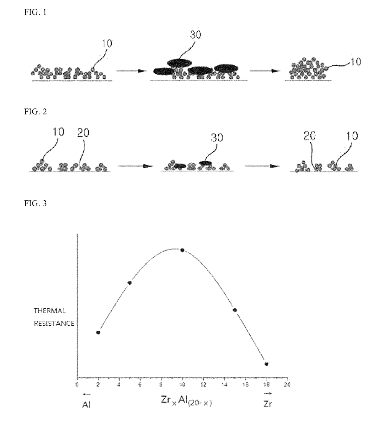
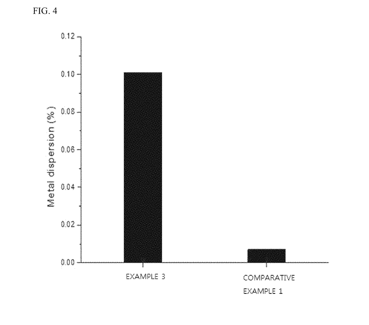
[0061]In order to assess stability against degradation of the monolith catalyst, an extent of sintering the catalytic active material was determined through CO chemisorption after performing heat treatment at 1000° C. for 24 hours. As shown in the following Table 1, in a case of the monolith catalyst including Al added as a barrier, it could be seen that CO adsorption quantity indicating the number of activation points is 5 to 12 times higher than the monolith catalyst without Al addition (Comparative Example 1). Furthermore, a dispersion rate of active ingredients was also found to be 6 to 14 times higher than Comparative Example 1.

[0062]In particular, at a molar ratio of Zr to Al of 1:1, the largest CO adsorption quantity and the highest metal dispersion rate were observed, thereby indicating that, due to the degradation, the most stable addition ratio of the barrier may be denoted by Zr:Al=1:1. This result could be demonstrated by the graph of FIG. 3 illustrating a change in ther...


PUM

PropertyMeasurementUnit
specific surface areaaaaaaaaaaa
temperatureaaaaaaaaaa

Abstract

The present invention relates to a monolith catalyst for reforming reaction, and more particularly, to a thermally stable (i.e. thermal resistance-improved) monolith catalyst for reforming reaction having a novel construction such that any one of Group 1A to Group 5A metals are used as a barrier component in the existing catalyst particles to inhibit carbon deposition occurring during the reforming reaction in a process for formation of a reforming monolith catalyst while improving thermal durability as well as non-activation of the catalyst due to a degradation.

Description

CROSS-REFERENCE TO RELATED APPLICATIONS[0001]This application claims priority to Korean Patent Application No. 10-2016-0095541, filed on Jul. 27, 2016 in the Korean Intellectual Property Office, the entire disclosure of which is incorporated herein by reference.FIELD OF THE INVENTION[0002]The present invention relates to a monolith catalyst for reforming reaction, and more particularly, to a thermally stable (i.e. thermal resistance-improved) monolith catalyst for reforming reaction having a novel construction, such that any one of Group 1A to Group 5A metals are used as a barrier component for preventing a growth of active particles in the existing catalyst particles to inhibit carbon deposition caused by the growth of catalyst particles occurring during the reforming reaction in a process for formation of a reforming monolith catalyst while improving thermal durability as well as non-activation of the catalyst due to a degradation.BACKGROUND OF THE INVENTION[0003]Due to a global w...

Claims


Application Information

Patent Timeline
Patent Type & Authority Patents(United States)
IPC IPC(8): B01J23/38B01J37/08B01J37/04B01J37/02B01J37/00B01J23/70B01J33/00C10G2/00B01J21/06C01G25/02C01G25/04
CPCC10G2/331B01J23/38B01J23/70B01J33/00C10G2/50B01J2229/24C01G25/02C01G25/04B01J37/0236B01J37/086B01J37/0219B01J23/002B01J23/8913B01J2523/00Y02P30/00B01J35/56B01J35/612B01J2523/31B01J2523/48B01J2523/821B01J2523/845B01J23/46B01J23/75B01J23/755B01J23/80B01J23/89B01J37/0018B01J37/0201B01J37/0215
Inventor HEO, IL JEONGYOU, YOUNG WOOPARK, JI HOONPARK, JUNG HYUNCHANG, TAE SUNKIM, BEOM SIKSUH, JEONG KWON
Owner KOREA RES INST OF CHEM TECH
Learn More