Fluid liner wear indicator for suction manifold of reciprocating pump assembly

a technology of reciprocating pump and wear indicator, which is applied in the direction of positive displacement liquid engine, liquid fuel engine, borehole/well accessories, etc., can solve the problems of fluid liner wear and/or erosion, short and frequent duty cycle of pumps,

Active Publication Date: 2018-10-30
SPM OIL & GAS INC
View PDF46 Cites 14 Cited by
  • Summary
  • Abstract
  • Description
  • Claims
  • Application Information

AI Technical Summary

Benefits of technology

[0009]In an exemplary embodiment, the fluid liner covers the wear indicator so that at least a portion of the fluid liner extends between the wear indicator and the longitudinal axis of the elongated member, thereby preventing the fluid that flows through the fluid chamber from contacting the wear indicator.
[0019]In an exemplary embodiment, the fluid liner covers the wear indicator so that at least a portion of the fluid liner extends between the wear indicator and the longitudinal axis of the elongated member, thereby preventing the fluid that flows through the fluid chamber from contacting the wear indicator.
[0029]In an exemplary embodiment, the wear indicator includes the wear body, the fluid liner covering the wear body so that at least a portion of the fluid liner extends between the wear body and the longitudinal axis of the elongated member, thereby initially preventing the fluid that flows through the fluid chamber from contacting the wear body.
[0039]In an exemplary embodiment, the wear indicator includes the wear body, the fluid liner covering the wear body so that at least a portion of the fluid liner extends between the wear body and the longitudinal axis of the elongated member, thereby preventing the fluid that flows through the fluid chamber from contacting the wear body.

Problems solved by technology

During such operations, these pumps are often subject to short and frequent duty cycles, and are required to deliver a fluid or slurry to the wellbore at pressures up to 20,000 psi.
The fluid liner is subject to wear and / or erosion due to the flow of the fluid therethrough and / or the dynamic response of the fluid liner to the pressure fluctuations within the manifold as the fluid flows therethrough.

Method used


Image

  • Fluid liner wear indicator for suction manifold of reciprocating pump assembly
  • Fluid liner wear indicator for suction manifold of reciprocating pump assembly
  • Fluid liner wear indicator for suction manifold of reciprocating pump assembly

Examples


Embodiment Construction

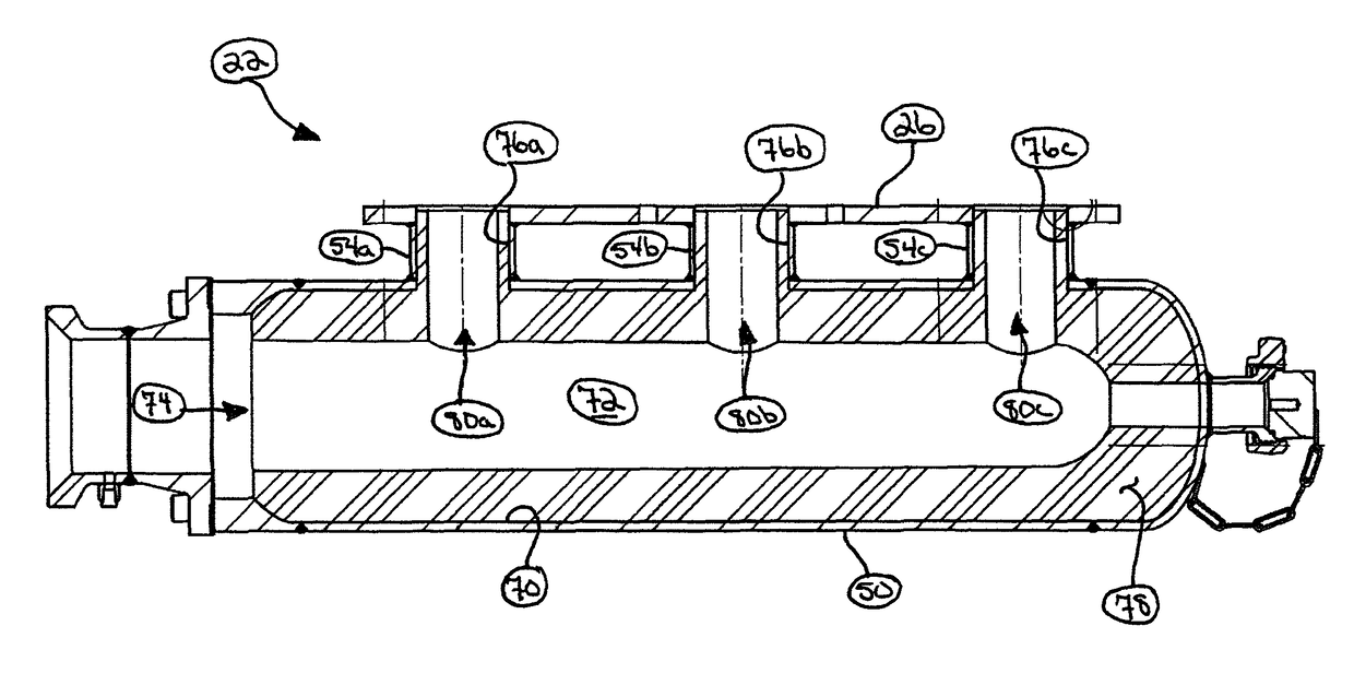
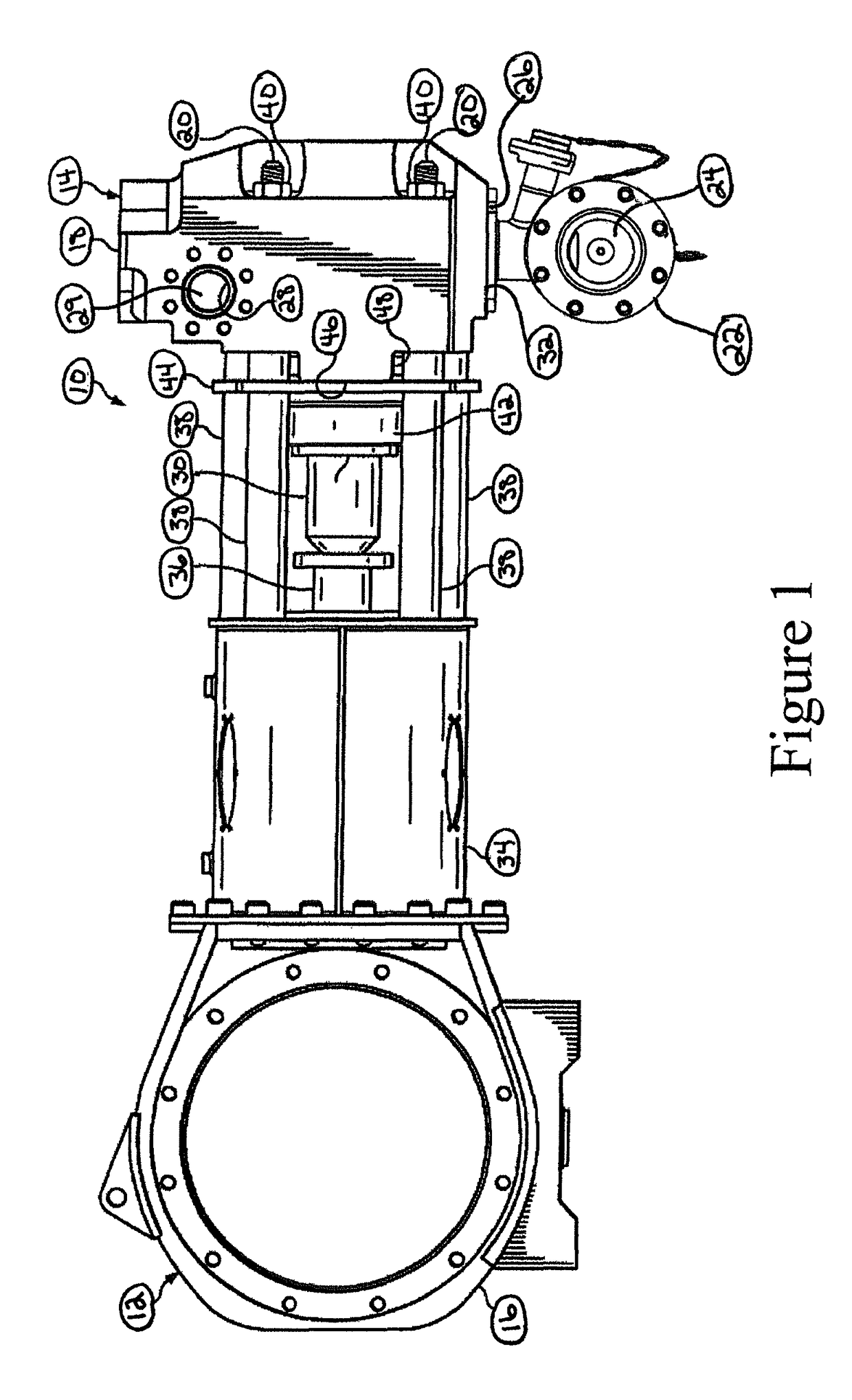
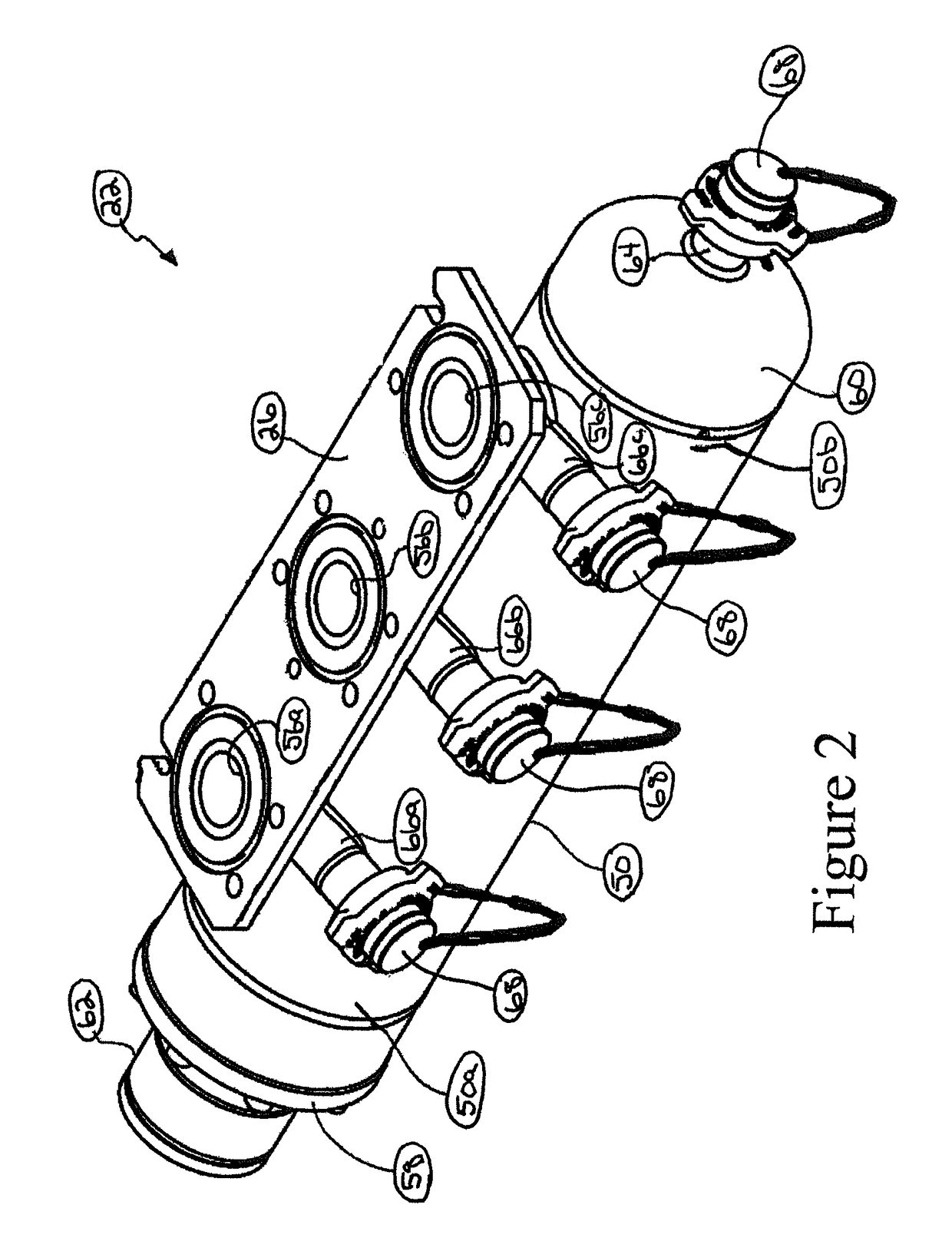
[0058]In an exemplary embodiment, as illustrated in FIG. 1, a reciprocating pump assembly is generally referred to by the reference numeral 10 and includes a power end portion 12 and a fluid end portion 14 operably coupled thereto. The power end portion 12 includes a crankshaft housing 16 in which a crankshaft (not shown) is disposed, the crankshaft being operably coupled to an engine or motor (not shown), which is adapted to drive the crankshaft. The fluid end portion 14 includes a fluid end block 18, which is connected to the crankshaft housing 16 via a plurality of stay rods 20, two of which are shown in FIG. 1. An inlet such as, for example, a suction manifold 22 is connected to the fluid end block 18 and includes an interior passage 24 and a mounting plate 26. The structure of the suction manifold 22 will be discussed in further detail below. The fluid end block 18 also includes a discharge manifold 28 that defines an interior passage 29, which is spaced in a parallel relation ...


PUM


Abstract

A manifold through which a fluid is adapted to flow. The manifold includes an elongated member at least partially defining a fluid chamber through which the fluid is adapted to flow, a longitudinal axis, and an interior surface; a fluid liner disposed within the fluid chamber and adapted to dynamically respond to pressure fluctuations within the fluid chamber as the fluid flows therethrough; and a wear indicator positioned radially between the interior surface of the elongated member and the longitudinal axis. The fluid liner is subject to wear and / or erosion due to the flow of the fluid therethrough and / or the dynamic response of the fluid liner to the pressure fluctuations within the fluid chamber. The wear indicator is adapted to indicate the degree to which the fluid liner has been subjected to the wear and / or erosion.

Description

CROSS-REFERENCE TO RELATED APPLICATION[0001]This application claims the benefit of the filing date of, and priority to, U.S. Application No. 62 / 183,141, filed Jun. 22, 2015, the entire disclosure of which is hereby incorporated herein by reference.TECHNICAL FIELD[0002]The present disclosure relates generally to a reciprocating pump and, more specifically, to enhancing the performance, reliability, and / or capacity of the reciprocating pump by equipping a fluid liner of the suction manifold of the reciprocating pump with a wear indicator according to the present disclosure.BACKGROUND OF THE DISCLOSURE[0003]Various pumps are used in connection with oilfield operations such as, for example, cementing, acidizing, or fracturing of a subterranean wellbore. During such operations, these pumps are often subject to short and frequent duty cycles, and are required to deliver a fluid or slurry to the wellbore at pressures up to 20,000 psi. An exemplary pump for oilfield operations is a reciproc...

Claims


Application Information

Patent Timeline
Patent Type & Authority Patents(United States)
IPC IPC(8): F16L41/02F16L41/03F16L55/033F16L55/04F04B53/14F04B53/16F16L57/06F04B19/22E21B43/26
CPCF16L41/026E21B43/26F04B19/22F04B53/14F04B53/16F16L55/0332F16L55/041F16L57/06F16L41/03Y10T137/8158F16L2201/30F04B15/02F04B47/00F04B51/00E21B43/27E21B43/2607
Inventor SHUCK, CHARLES BEN
Owner SPM OIL & GAS INC
Why Eureka
Try Eureka