System and method of optical axis alignment monitor and feedback control for a spectrometer

a technology monitor, which is applied in the field of system and method of optical axis alignment monitor and feedback control for a spectrometer, can solve the problems of increasing the load of required instrumentation resources (mass, power, volume, complexity, etc., to achieve the effect of maximizing science image quality and degrading scientific image integrity

Inactive Publication Date: 2018-10-30
NASA
View PDF1 Cites 5 Cited by
  • Summary
  • Abstract
  • Description
  • Claims
  • Application Information

AI Technical Summary

Benefits of technology

[0007]The present invention relates to a system and method of a real-time, monitoring and control feedback system for a 2-D spectrometer application, to correct for active optical axis pointing misalignments or jitter (i.e., tip, tilt), that result in degraded scientific image integrity and unwanted spatial crosstalk and imaging blurring art...

Problems solved by technology

Uncompensated optical axis motions introduce unwanted imaging misalignments and image blurring artifacts, thus, highly degrading high-resolution science image data.
In addition, current ground image processing techniques are unable to isolate these image motion effects, and thus, they remain as uncorrectable and undesired image artifacts (e.g., spectral and spatial blurring—i.e., crosstalk).
This greatly increase...

Method used


Image

  • System and method of optical axis alignment monitor and feedback control for a spectrometer
  • System and method of optical axis alignment monitor and feedback control for a spectrometer
  • System and method of optical axis alignment monitor and feedback control for a spectrometer

Examples


Embodiment Construction

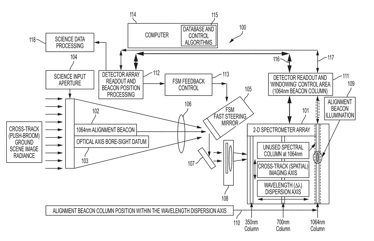
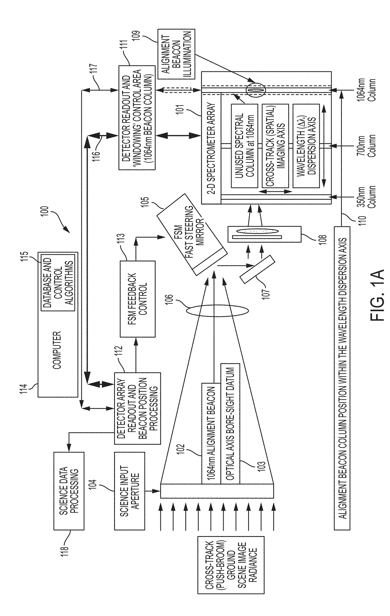
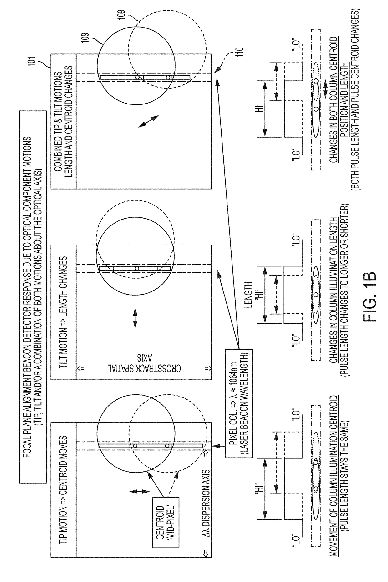
[0051]The present invention relates to an apparatus and method of a real-time, monitoring and control feedback system for a 2-D spectrometer application, to correct for active optical axis pointing misalignments or jitter (i.e., tip, tilt), that result in degraded scientific image integrity and unwanted spatial crosstalk and imaging blurring artifacts, which severely limit the applications for science image data. The present invention provides a unique system architecture which ensures the most direct optical axis motion detection and correction control capability that will enable sub-pixel image motion monitoring and boresight control stability, thus, maximizing the science image quality.

[0052]In one embodiment, the present invention relates to a push-broom spectrometer, which can be used, for example, in a spectrometer application at a geosynchronous orbit. In one exemplary embodiment, since geosynchronous instrument and spacecraft platform technology allows for approximately + / −1...


PUM


Abstract

The present invention relates to an apparatus and method of a real-time, monitoring and control feedback system for a 2-D spectrometer application, to correct for active optical axis pointing misalignments or jitter (i.e., tip, tilt), that result in degraded scientific image integrity, unwanted spatial crosstalk and image blurring artifacts which severely limit the applications for high resolution spectrometer image data. The present invention provides a unique system architecture which ensures the most direct optical axis motion detection and control capability that will enable sub-pixel image motion monitoring and boresight control stability, thus, maximizing the science image quality.

Description

ORIGIN OF THE INVENTION[0001]The invention described herein was made by an employee of the United States Government, and may be manufactured or used by or for the Government for governmental purposes without the payment of any royalties thereon or therefor.BACKGROUND OF THE INVENTION1. Field of the Invention[0002]The present invention is related to providing a real time optical axis alignment monitor and feedback control system for a 2-dimensional (2-D) push-broom spectrometer application, to correct for internal optical component motions that would induce boresight pointing errors and image blurring during the scene sampling integration period.2. Description of the Related Art[0003]Uncompensated optical axis motions introduce unwanted imaging misalignments and image blurring artifacts, thus, highly degrading high-resolution science image data. In addition, current ground image processing techniques are unable to isolate these image motion effects, and thus, they remain as uncorrect...

Claims


Application Information

Patent Timeline
IPC IPC(8): G01J3/28G01J3/02
CPCG01J3/0289G01J3/027G01J3/0208G01J3/2823G01J3/2803G01J3/021G01J3/04G01J3/06
Inventor MARX, CATHERINELINARES, IRVINGSHU, PETERSMITH, JAMES
Owner NASA
Why Eureka
Try Eureka