Photonic microwave mixing apparatus and method thereof

a mixing apparatus and microwave technology, applied in the field of photonic microwave mixing apparatus and method, can solve the problems of inability to provide high-frequency microwave mixing, high system power consumption, and inability to achieve highly precise optical phase difference between the two interfering optical signals, etc., to achieve the effect of reducing the need for high-frequency yet expensive electronics, broad spectral range, and low phase noise level

Active Publication Date: 2018-10-30
NAT CHENG KUNG UNIV
View PDF13 Cites 0 Cited by
  • Summary
  • Abstract
  • Description
  • Claims
  • Application Information

AI Technical Summary

Benefits of technology

[0031]Accordingly, the photonic microwave mixing apparatus and method based upon the present invention possess one or more of the following characteristics and advantages:
[0033](2) The semiconductor laser used in the apparatus and method of the present invention functions both as a microwave mixer and a microwave local oscillator at the same time. Because of the all-optical nature of the present invention, not only the needs for high-frequency yet expensive electronics are largely reduced, but also a considerably broad spectral range from a few gigahertz to hundreds of gigahertz can be achieved for either frequency upconversion or downconversion without suffering from the bandwidth limitation of electronics. These features make the apparatus and method of the present invention dynamically reconfigurable for different wireless communication networks requiring different operating microwave frequencies.
[0034](3) Since the frequency-converted microwave signal possesses a narrow linewidth and a low phase noise level, the apparatus and method of the present invention are beneficial for the next generation wireless systems to adopt advanced modulation formats for data transmission in order to further increase the communication capacity.
[0035](4) Compared with the optical modulation depth of the optical input which is typically lower than 10%, the optical modulation depth of the optical output can be made close to 100%. This indicates that, under the same optical power level received by a photodetector, the power of the frequency-converted microwave signal is significantly higher than that of the frequency-to-be-converted microwave signal. This in turn suggests that the present invention exhibits high conversion efficiency, which is advantageous in improving the detection sensitivity, fiber transmission distance, and link gain of a communication network.

Problems solved by technology

However, since an electronic microwave local oscillator is required, high-frequency microwave mixing may not be available due to the bandwidth limitation of the electronic microwave local oscillator.
In addition, since a high output power from the electronic microwave local oscillator is required for high conversion efficiency and an optical power amplifier is needed to compensate for the significant power loss after the process of the optical filtering, the system power consumption is considerably high.
However, one major disadvantage of this method is that a highly precise optical phase difference between the two interfering optical signals is needed, which requires high stability of the conversion system against ambient variations and system adjustments.
In addition, since a high-power electronic microwave local oscillator is required for high conversion efficiency, not only high-frequency microwave mixing may not be available due to the bandwidth limitation of the electronic microwave local oscillator, but also the system power consumption is considerably high.
However, since an electronic microwave local oscillator is required, high-frequency microwave mixing may not be available due to the bandwidth limitation of the electronic microwave local oscillator.
In addition, since a high output power from the electronic microwave local oscillator is required for high conversion efficiency and an optical power amplifier is needed to compensate for the significant power loss after the process of the optical filtering, the system power consumption is considerably high.

Method used


Image

  • Photonic microwave mixing apparatus and method thereof
  • Photonic microwave mixing apparatus and method thereof
  • Photonic microwave mixing apparatus and method thereof

Examples


Embodiment Construction

[0052]To illustrate the device structure, operating principle, and advantageous characteristics of the present invention, a preferred embodiment and the corresponding drawings are provided with more details. The purpose of the drawings being used is for illustration, and they are not necessarily the real proportion and precise allocation of the embodiments of the present invention. Therefore, they should not be used to limit the privilege coverage of the practical embodiments of the present invention.

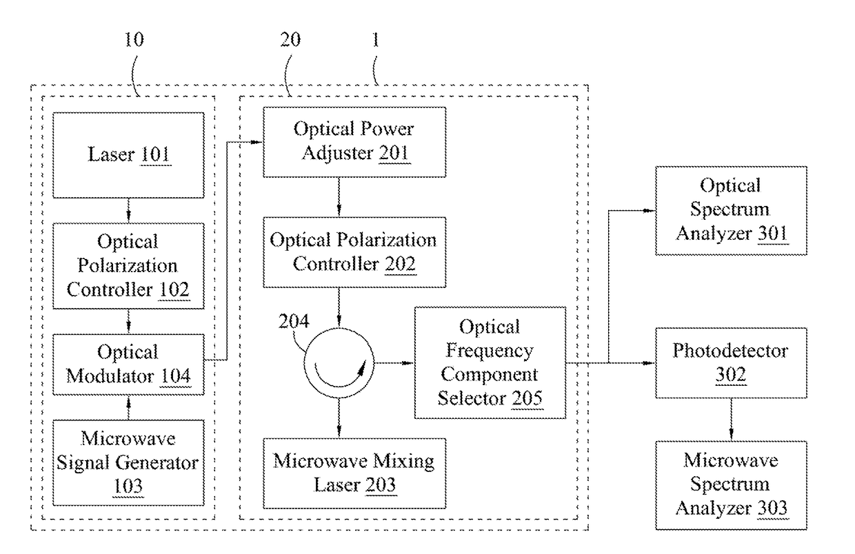
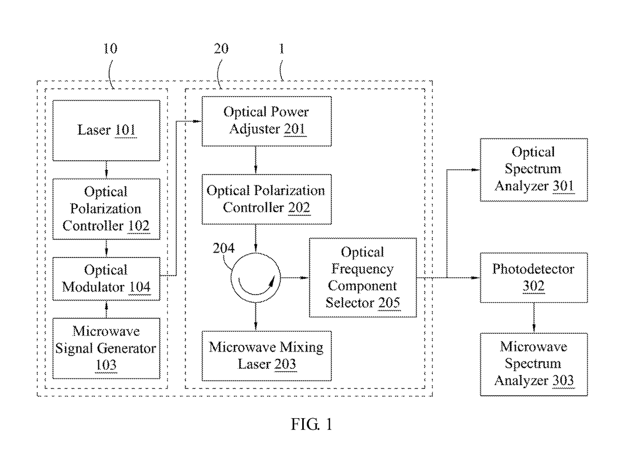
[0053]Referring to FIG. 1, FIG. 1 is a schematic representation of a photonic microwave mixing apparatus according to a preferred embodiment of the present invention. As shown in FIG. 1, a photonic microwave mixing apparatus 1 includes a photonic microwave mixing module 20. The photonic microwave mixing module 20 converts an optical input, which is an optical signal carrying a frequency-to-be-converted microwave signal, into an optical output, which is an optical signal carrying a frequ...


PUM

PropertyMeasurementUnit
oscillation frequency f0aaaaaaaaaa
offset frequencyaaaaaaaaaa

Abstract

A photonic microwave mixing apparatus and method thereof are disclosed. An optical input carrying a frequency-to-be-converted microwave signal is injected into a photonic microwave mixing module of the photonic microwave mixing apparatus, wherein the photonic microwave mixing module includes a microwave mixing laser. The optical power and carrier frequency of the optical input are adjusted so as to place the microwave mixing laser in period-one nonlinear dynamics, and, at the same time, to achieve frequency-unlocking between the oscillation sidebands of the period-one nonlinear dynamics and the modulation sidebands of the optical input. Under such operation, the microwave mixing laser emits a nonlinear wave-mixing optical signal. Properly selecting the frequency components of the nonlinear wave-mixing optical signal through an optical frequency component selector generates an optical output carrying a frequency-converted microwave signal, therefore achieving microwave frequency conversion.

Description

CROSS-REFERENCE TO RELATED APPLICATION[0001]This application claims priority from Taiwan Patent Application No. 105125868, filed on Aug. 12, 2016 in Taiwan Intellectual Property Office, the contents of which are hereby incorporated by reference in their entirety.BACKGROUND OF THE INVENTION[0002]1. Field of the Invention[0003]The present invention relates to a photonic microwave mixing apparatus and method thereof by using, particularly, period-one nonlinear dynamics of semiconductor lasers.[0004]2. Description of the Related Art[0005]According to the statistics released by a leading telecommunication manufacturer, Cisco Systems, Inc, the data traffic of the global wireless communication has reached an average close to 3.7 million terabytes per month in 2015 and will continue to grow at a compound annual rate of 53% in the following years. In order to meet such a huge data traffic demand, telecommunication operators and manufacturers have proposed two solutions. On one hand, they hav...

Claims


Application Information

Patent Timeline
Patent Type & Authority Patents(United States)
IPC IPC(8): H04B10/50G02F1/35H04B10/2575H04B10/564H04B10/516
CPCH04B10/564G02F1/353H04B10/2575H04B10/503H04B10/516H04B10/501H04B2210/006H04B10/25752
Inventor HWANG, SHENG-KWANGHUNG, YU-HAN
Owner NAT CHENG KUNG UNIV
Why Eureka
Try Eureka