Bias Member for the Doctor Blade of the Developer Unit in an Imaging Device

a technology of developer unit and blade, which is applied in the direction of electrographic process apparatus, instruments, optics, etc., can solve the problems of non-uniform nip pressure between the doctor and the doctor, inconsistent toner presented to the latent image on the photoconductive drum, and inability to meet the needs of the patient, etc., to achieve less defects, less heat, and longer life of the developer uni

Active Publication Date: 2013-07-18
LEXMARK INT INC
View PDF3 Cites 0 Cited by
  • Summary
  • Abstract
  • Description
  • Claims
  • Application Information

AI Technical Summary

Benefits of technology

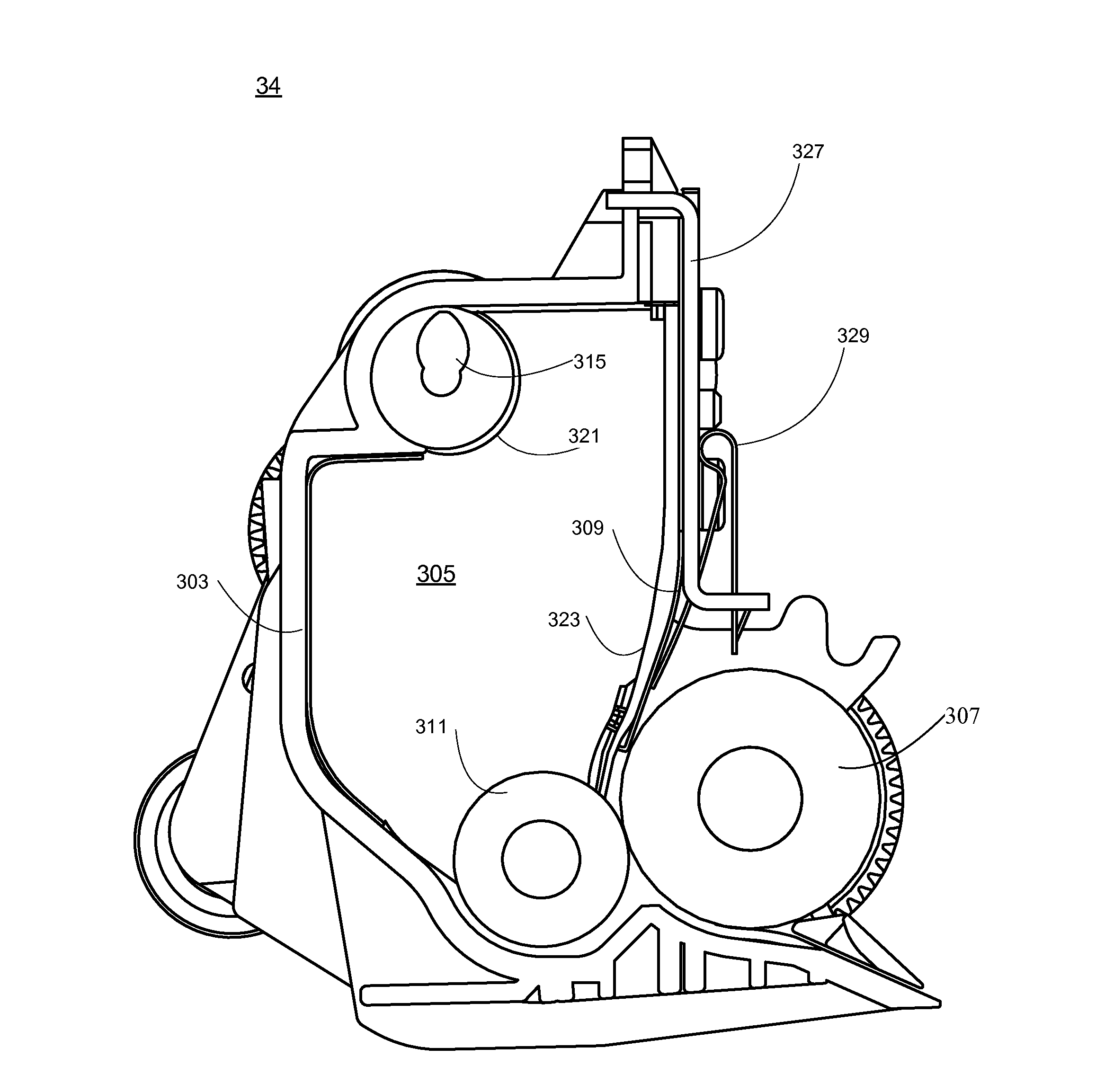
[0012]Example embodiments of the present disclosure overcome shortcomings of existing developer units and thereby satisfy a significant need for a developer unit which serves to at least partly offset forces presented to the doctor blade and developer roll by the J-seals of the developer unit. In accordance with an example embodiment, there is disclosed a developer unit housing; a developer roll disposed within the housing and having a shaft which extends from at least one side thereof; and at least one seal member coupled within the housing along the at least one side thereof, a portion of the at least one seal member engaging the developer roll so as to prevent toner from leaking from the housing. In addition, the developer unit includes a doctor blade assembly coupled to the housing, including a support bracket for securement of the blade assembly within the housing, a doctor blade coupled to the support bracket and positioned so that a distal end thereof is disposed between and engages with the developer roll and the at least one seal member, and at least one bias member having a first end portion coupled to the support bracket and a second end portion which engages with the doctor blade so as to present a force that at least partly offsets a force presented to the doctor blade and developer roll by the at least one seal member. By providing a force at least partly offsetting the force presented by the seal member, the pressure between the doctor blade and developer roll is more uniform with less heat generated during printing which results in less defects and longer developer unit life. The more uniform pressure also provides a more uniform mass and charge of the layer of toner on the developer roll. The use of a bias member at each end of the doctor blade results in the doctor blade having less wear at its ends.

Problems solved by technology

Without a doctor blade, the coating of toner on the developer roll may be inconsistent, too thick, too thin or bare, thereby causing the amount of toner presented to the latent image on the photoconductive drum to be inconsistent and the level of darkness of the printed image may vary as a result, which is considered a print defect.
One challenge with existing doctor blade assemblies is that of providing a consistent seal generally around the location where the doctor blade assembly, the developer roll and the developer unit housing meet.
Such contact results in nonuniform nip pressure between the doctor blade and the developer roll by providing a greater force at the ends thereof than the middle.
The greater force between the doctor blade and the developer roll also generates more heat at the ends of the doctor blade, thereby resulting in shorter life of the doctor blade and developer unit.
The greater force at the ends of doctor blade increases the wear rate of the doctor blade and shortens the life of the doctor blade.
The heat generated may potentially cause toner to melt on the developer roll, which will damage the developer unit.

Method used


Image

  • Bias Member for the Doctor Blade of the Developer Unit in an Imaging Device
  • Bias Member for the Doctor Blade of the Developer Unit in an Imaging Device
  • Bias Member for the Doctor Blade of the Developer Unit in an Imaging Device

Examples


Embodiment Construction

[0027]It is to be understood that the present disclosure is not limited in its application to the details of construction and the arrangement of components set forth in the following description or illustrated in the drawings. The present disclosure is capable of other embodiments and of being practiced or of being carried out in various ways. Also, it is to be understood that the phraseology and terminology used herein is for the purpose of description and should not be regarded as limiting. The use of “including,”“comprising,” or “having” and variations thereof herein is meant to encompass the items listed thereafter and equivalents thereof as well as additional items. Unless limited otherwise, the terms “connected,”“coupled,” and “mounted,” and variations thereof herein are used broadly and encompass direct and indirect connections, couplings, and mountings. In addition, the terms “connected” and “coupled” and variations thereof are not restricted to physical or mechanical connec...


PUM


Abstract

A doctor blade assembly for the developer unit of an electrophotographic imaging system. The doctor blade assembly includes a blade member having a first longitudinal edge for contacting a developer roll of an imaging system; a bracket member operatively connected to the blade member; and at least one bias member having a first end portion along a first longitudinal end portion of the bracket member and a second end portion contacting a distal portion of the blade member so as to present a force thereon. The force presented by the bias member serves as a counterforce to at least partly offset a force presented on the doctor blade and developer roll by a seal member of the developer unit.

Description

CROSS REFERENCES TO RELATED APPLICATIONS[0001]Pursuant to 35 U.S.C. §119, this application claims the benefit of the earlier filing date of Provisional Application Ser. No. 61 / 586,102, filed Jan. 12, 2012, entitled “Bias Member for the Doctor Blade of the Developer Unit in an Imaging Device,” the content of which is hereby incorporated by reference herein in its entirety.STATEMENT REGARDING FEDERALLY SPONSORED RESEARCH OR DEVELOPMENT[0002]None.REFERENCE TO SEQUENTIAL LISTING, ETC.[0003]None.BACKGROUND[0004]1. Field of the Disclosure[0005]The present disclosure relates generally to electrophotographic imaging devices such as a printer or multifunction device having printing capability, and in particular to a mechanism for counterbalancing forces that are presented onto the doctor blade of an electrophotographic device's developer unit by end seals thereof.[0006]2. Description of the Related Art[0007]Laser printers utilize a light beam which is focused to expose a discreet portion of ...

Claims


Application Information

Patent Timeline
Patent Type & Authority Applications(United States)
IPC IPC(8): G03G15/08
CPCG03G15/0812G03G21/0029
Inventor GIBSON, NICHOLAS FENLEYMATTINGLY, BRAD EDWARDNEWMAN, BENJAMIN KEITH
Owner LEXMARK INT INC
Why Eureka
Try Eureka