Apparatus for Drawing of a Bodily Fluid and Method Therefor

a bodily fluid and apparatus technology, applied in medical science, vaccination/ovulation diagnostics, surgery, etc., can solve the problems of significant patient distress, blood leakage under the skin to give rise to hematoma, and difficulty in collecting bodily fluids in sufficient volumes for reliable testing

Active Publication Date: 2016-07-14
ROC8SCI
View PDF11 Cites 1 Cited by
  • Summary
  • Abstract
  • Description
  • Claims
  • Application Information

AI Technical Summary

Benefits of technology

[0010]The present invention enables analysis of a test sample without some of the costs and disadvantages of the prior art. Embodiments of the present invention enable content-rich analysis of small-volume test samples of liquids or moist solids, such as chemical solutions, petroleum products (e.g., fuel oils, crude oil, waste oils, etc.), bodily fluids (e.g., blood, urine, spittle, sweat, tears, saliva, stool, etc.), foodstuffs (e.g., dairy products, pastes, sauces, etc.), cosmetic compounds, and the like, thereby obviating the need for drawing and storing large volumes of material.
[0011]The present invention encompasses two key inventive aspects: 1) a sample holder that is easy to fabricate and low cost, but that enables spectroscopic analysis of a test sample using mid-infrared radiation; and 2) a microfluidic system that is dimensioned and arranged to facilitate the rapid filling of a chamber with a liquid without inducing bubbles in the liquid, where the force that draws the liquid into the chamber is capillary force.
[0012]An illustrative embodiment of the present invention is a compact sample holder operative for drawing blood from a draw site on a patient via capillary force and without causing bubbles to form during the draw. The sample holder comprises a draw tube and a small-volume, two-part sample chamber, which includes a sample region and a capillary channel. The sample holder is transmissive for mid-infrared radiation, which enables spectroscopic analysis of the blood over a short interaction length with the test sample. As a result, the sample holder requires only a small-volume sample chamber, which mitigates the need for drawing large volumes of blood from the patient. The patient, therefore, is not subjected to significant pain, discomfort, or long draw times.
[0015]The sample chamber is a circular region having a volume that is equivalent to approximately 1 / 50th of a drop of blood. It is defined by top and bottom surfaces that are closely spaced and substantially parallel, and a sidewall that is oriented an angle of approximately 45° to the top and bottom surfaces. The spacing of the top and bottom surfaces in the sample region enable development of capillary force for drawing liquid into the sample region, while the bottom surface and the sidewall collectively define a small triangular cross-section for the capillary channel, which fluidically couples the sample chamber with the draw tube. The small cross-sectional spacing of the sample region and capillary channel gives rise to a strong capillary force that enhances the capillary drawing capability of the sample holder and inhibits the formation of bubbles in the sample as it is drawn into the sample chamber. In some embodiments, the angle of the sidewall, with respect to the top and bottom surfaces, is less than 45°. In some embodiments, the sidewall is a non-planar surface.

Problems solved by technology

Unfortunately, the collection of bodily fluids in volumes sufficient for reliable testing can be challenging.
For example, conventional blood-test samples are usually drawn in-vivo using large medical syringes, which can cause significant patient distress—before, during, and after the drawing procedure.
As a result, the other end wall of the target vein is punctured, which can cause blood leakage under the skin to give rise to a hematoma.
Unfortunately, this method also has many disadvantages.
First, lancelet-based blood drawing typically yields only a small amount of blood before clotting occurs.
The presence of a blood clot in a blood sample is a cause for rejection of the sample because testing of partially clotted blood can lead to irregularities in some blood tests.
Second, sites that are prone to provide more blood when pierced also tend to have a high concentration of pain receptors.
As a result, a puncture of the skin at these sites typically causes the patient more pain.
Both blood-drawing methods cause significant pain to the patient, weep internally and externally afterward, give rise to potential infection sites, and are prone to bruising and prolonged tenderness.
As a result, patients are understandably unenthusiastic about having their blood drawn.
Further, a typical test panel requires several milliliters (or tens of milliliters) of blood.
This is true for other bodily fluids—urine, spittle, synovial fluid, moist solids, etc., which, in many cases, can be difficult to collect from the patient in sufficient volume.

Method used


Image

  • Apparatus for Drawing of a Bodily Fluid and Method Therefor
  • Apparatus for Drawing of a Bodily Fluid and Method Therefor
  • Apparatus for Drawing of a Bodily Fluid and Method Therefor

Examples


Embodiment Construction

[0038]The following terms are defined for use in this Specification, including the appended claims:[0039]“Mid-infrared radiation” (MIR) is defined as electromagnetic radiation having a wavelength within the range of approximately 2.5 microns to approximately 12.5 microns.[0040]“Transmissive” is defined as having a transmission of at least 45%. For example, an element that is transmissive for mid-infrared radiation transmits at least 45% of any light signal having a wavelength within the range of approximately 2.5 microns to approximately 12.5 microns.

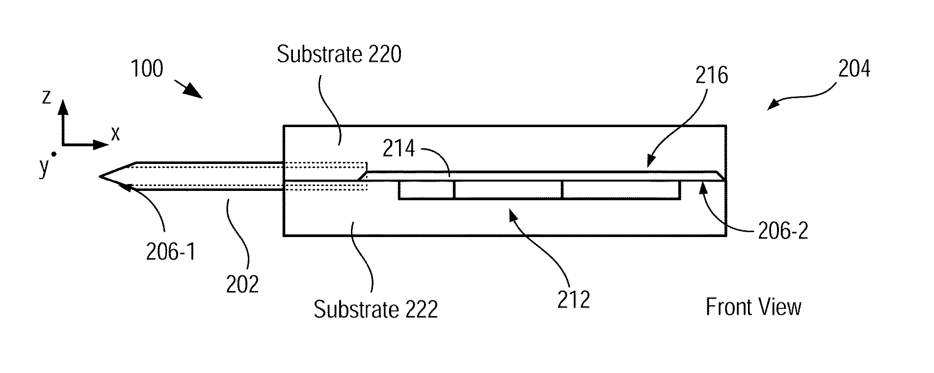
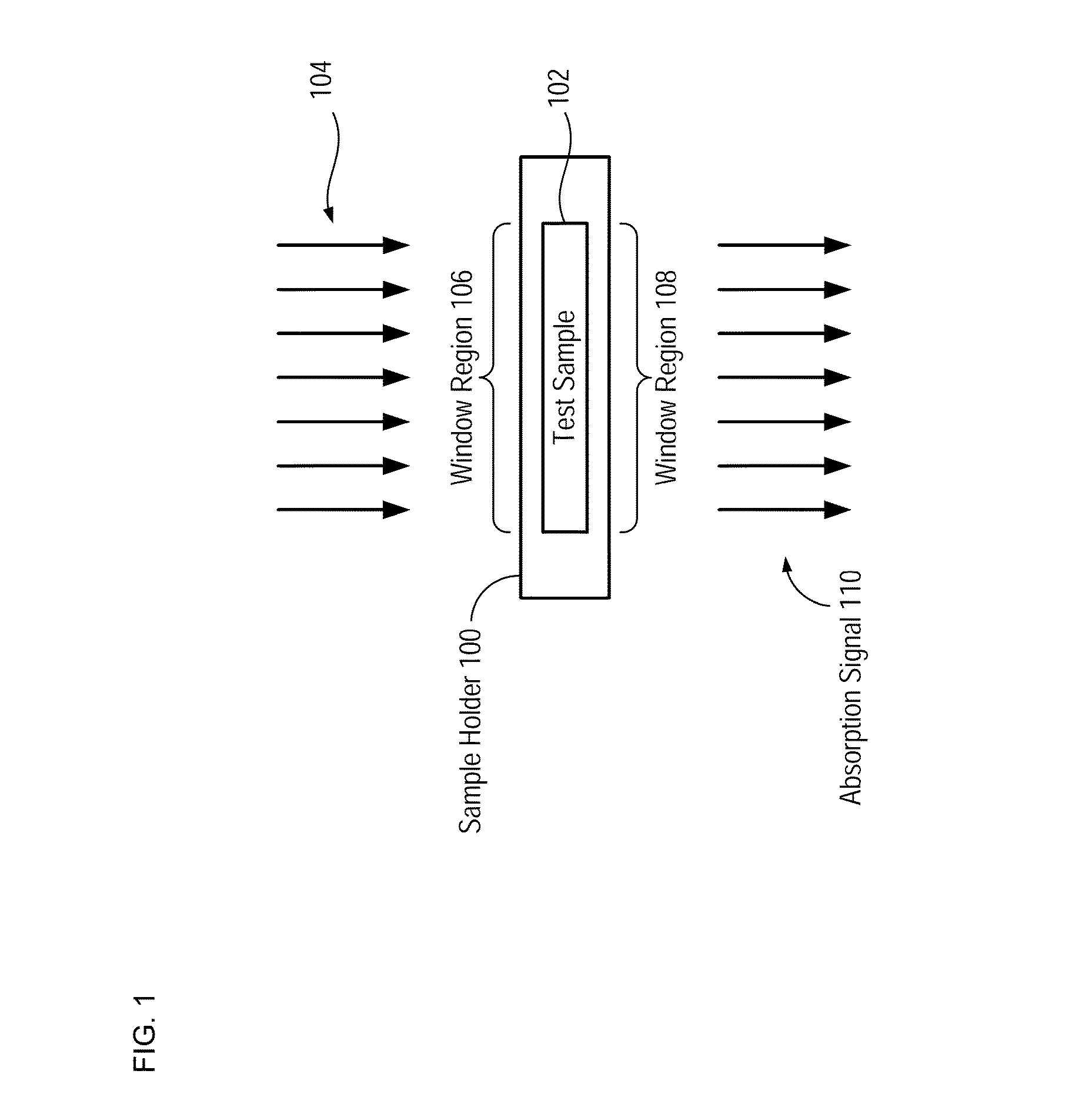
[0041]FIG. 1 depicts a schematic drawing of a sample holder in accordance with an illustrative embodiment of the present invention. Sample holder 100 is “microcuvette” operative for holding a minute volume of a liquid test sample. Sample holder 100 enables spectroscopic analysis of test sample 102 using mid-infrared radiation (i.e., radiation 104).

[0042]As discussed in U.S. Pat. No. 8,344,323, which is incorporated herein by reference, ...


PUM


Abstract

A sample holder that enables mid-infrared spectroscopy of a test sample using mid-infrared light is disclosed. The sample holder includes an inlet port and a sample chamber that comprises a sample region and a capillary channel that fluidically couples the inlet port and the sample region. The capillary channel is characterized by a higher capillary force than the sample region. As a result, when the inlet port is put in contact with a liquid containing the test sample, the liquid is drawn into the sample region without the formation of bubbles that could obscure the optical analysis. In some embodiments, the inlet port is the free end of a draw tube having an outer diameter that is smaller than the minimum spacing between pain receptors at a draw site on a patient, which mitigates pain felt by the patient due to insertion of the draw tube at the draw site.

Description

CROSS REFERENCE TO RELATED APPLICATIONS[0001]This application claims the benefit of U.S. Provisional Application Ser. No. 62 / 125,105, filed Jan. 14, 2015, entitled “Methods for the Painless Drawing of Aliquots of Bodily Fluids and Their Analytics,” and U.S. Provisional Application Ser. No. 62 / 197,298, filed Jul. 27, 2015, entitled “A Micro-Cuvette for the Painless Drawing of Aliquots of Bodily Fluids and Their Optical Analysis,” (Attorney Docket: 550-006PR2), each of which is incorporated herein by reference. If there are any contradictions or inconsistencies in language between this application and one or more of the cases that have been incorporated by reference that might affect the interpretation of the claims in this case, the claims in this case should be interpreted to be consistent with the language in this case.FIELD OF THE INVENTION[0002]The present invention relates to analytical chemistry technology in general, and, more particularly, to chemical analysis of fluids and f...

Claims


Application Information

Patent Timeline
Patent Type & Authority Applications(United States)
IPC IPC(8): A61B10/00A61B5/15B01L3/00
CPCA61B10/0045B01L3/502715B01L3/50273A61B5/150343A61B5/150755B01L2300/0645B01L2300/0672B01L2200/027B01L2300/0838B01L2300/0858B01L2400/0406A61B5/150022A61B5/150251A61B5/150389A61B5/150503A61B5/15105A61B5/15142B01L2200/0684B01L2300/0681B01L2300/0816
Inventor HARTLEY, FRANK THOMAS
Owner ROC8SCI
Why Eureka
Try Eureka