Device and method for protecting spring-biased conductor elements

a technology of conductor elements and devices, applied in the direction of two-part coupling devices, coupling device connections, antenna connectors, etc., can solve the problems of at least one conductor, linemen to improperly/incorrectly join connectors, and at least one of the conductors to be damaged, so as to prevent the damage of the fingers and mitigate the deformation of the plastic of the fingers

Active Publication Date: 2018-11-06
JOHN MEZZALINGUA ASSOC LLC
View PDF21 Cites 11 Cited by
  • Summary
  • Abstract
  • Description
  • Claims
  • Application Information

AI Technical Summary

Benefits of technology

[0012]A connector is provided including first and second connector portions each comprising electrically-connecting inner and outer conductors. A insert interposes the spring-biased fingers of an outer conductor basket of one of the connectors to prevent damage to the fingers in an unassembled condition / state, thereby ensuring electrical connectivity of the fingers in an assembled condition / state. In one embodiment, a collapsible protective insert includes an insert ring disposed around the spring-biased fingers and a plurality of spiral springs projecting axially from one side of the insert ring. In an unassembled condition / state, the spiral springs maintain the position of the insert ring relative to the spring-biased fingers to mitigate plastic deformation of the fingers in a radially outboard direction. In an assembled condition / state, the spiral springs nest with the insert ring in response to a compressive load applied to the other side of the insert ring as the first and second connector portions are coupled.
[0013]In another embodiment, a static insert comprises a plurality of radial members projecting from an inner ring disposed around an inner conductor of the first connector. In this embodiment, a radial gap is produced between an outer peripheral edge of the radial members and the compliant fingers of the first connector. In an unassembled condition / state, the static insert prevents ingress of an improperly-sized outer conductor sleeve. In an assembled condition, a cylindrical sleeve of the second connector slides into the radial gap to make electrical contact with the spring-biased fingers of the first connector.

Problems solved by technology

The geometric similarity between connectors, in combination with the difficulty associated with physically making a connection, i.e., fifty (50) feet in the air, can cause Linemen to improperly / incorrectly join connectors.
While improperly-mated connectors will not affect a viable telecommunications connection, an attempt to join the connectors can damage or, otherwise distort, at least one of the conductors.
Particularly vulnerable are the fingers of the outer conductor basket.
Inasmuch as the connector is often an integral component of an electronic component, i.e., the Remote Radio Unit, a seemingly small amount of damage to the integral connector can incapacitate a very costly piece of telecommunications equipment, e.g., ranging from 20K to 40K dollars, to replace.

Method used


Image

  • Device and method for protecting spring-biased conductor elements
  • Device and method for protecting spring-biased conductor elements
  • Device and method for protecting spring-biased conductor elements

Examples


Embodiment Construction

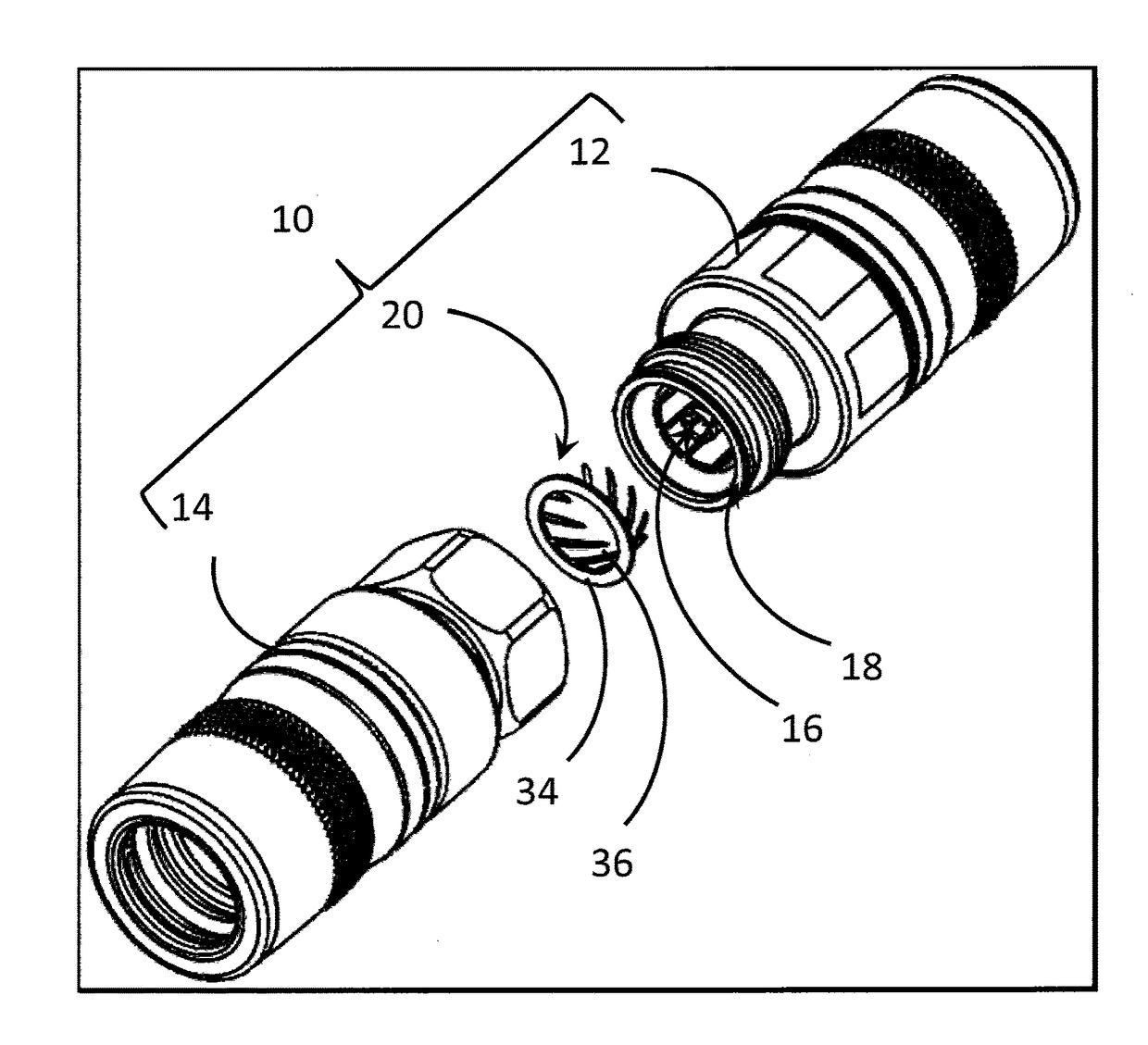
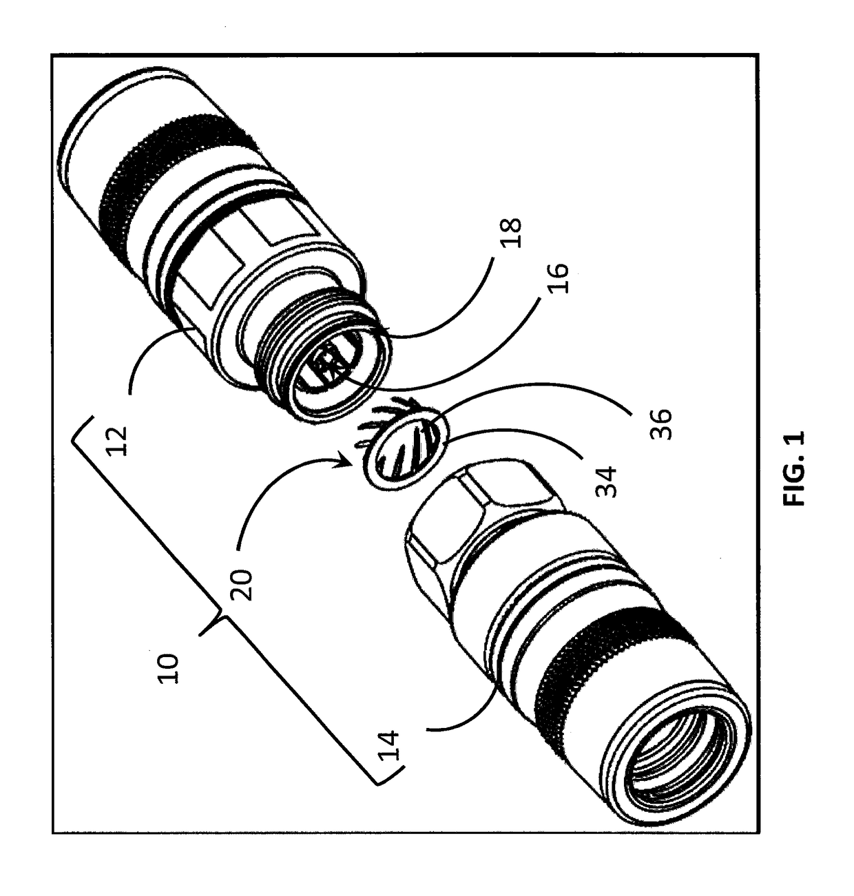
[0014]The following describes a Mini-DIN connector and a protective insert for mitigating damage to the multi-fingered spring-biased outer conductor basket of the Mini-DIN connector. While the insert is particularly useful for Mini-DIN connectors, it should be appreciated that the protective insert, and the teachings associate therewith are applicable to a wide-variety of telecommunications / signal connectors. The protective insert 20 of the present disclosure has utility when the Mini-DIN Connector is unassembled, or is being prepared for assembly. Specifically, the insert 20 prevents damage to a Mini-DIN connector, i.e., one half of the connector, in the event that a connector of a different size or variety is forcibly urged into engagement with the Mini-DIN connector. As such, a costly error may be obviated through the use of the protective insert.

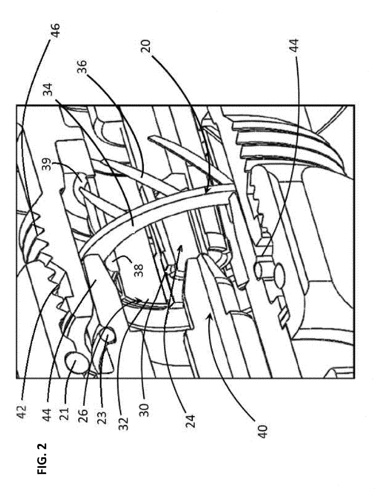
[0015]In FIGS. 1 and 2, a connector 10 is depicted including first and second connectors 12 and 14 each having an inner conductor 16 an...


PUM


Abstract

A connector including first and second connector portions each comprising electrically-connecting inner and outer conductors and an inhibitor interposing the inner and outer conductors configured to inhibit the inadvertent insertion of a non-mating connector between the inner and outer conductors. In one embodiment an insert is disposed over a plurality of spring-biased fingers of the outer conductor to prevent deformation of the fingers in an unassembled condition / state by insertion of the non-mating connector. In another embodiment, the insert includes a plurality of radial members disposed between a central hub and an outer ring to prevent insertion of the non-mating connector.

Description

CROSS-REFERENCE TO RELATED APPLICATIONS[0001]This application is a non-provisional patent application of, and claims the benefit and priority of, U.S. Provisional Patent Application No. 62 / 162,029 filed on May 15, 2015. The entire contents of such application is hereby incorporated by reference.BACKGROUND[0002]Telecommunications systems often employ hardline connectors for data transfer between telecom components, e.g., a Remote Radio Unit (RRU) and a telecommunications sector antenna. These hardline connectors often employ an arrangement of spring-biased fingers / elements for making the requisite electrical connections, e.g., signal or electrical ground connections, from one connector to an opposing connector. One type of connector, known as a Mini-Din Connector, employs a multi-fingered inner conductor socket surrounded by a multi-fingered outer connector basket which receive an inner conductor pin and an outer conductor sleeve, respectively, of an adjoining / opposing connector.[000...

Claims


Application Information

Patent Timeline
Patent Type & Authority Patents(United States)
IPC IPC(8): H01R13/44H01R24/40H01R13/6583
CPCH01R24/40H01R13/6583H01R2201/02
Inventor STEVENS, BRANDON M.WILD, WERNER
Owner JOHN MEZZALINGUA ASSOC LLC
Why Eureka
Try Eureka