Communication connector
a technology of communication connectors and connectors, applied in the direction of coupling devices, two-part coupling devices, electrical equipment, etc., can solve the problems of signal reflection and communication quality reduction, and the interval between wires may change a large amount, so as to suppress the effect of communication quality reduction
- Summary
- Abstract
- Description
- Claims
- Application Information
AI Technical Summary
Benefits of technology
Problems solved by technology
Method used
Image

Examples
first embodiment
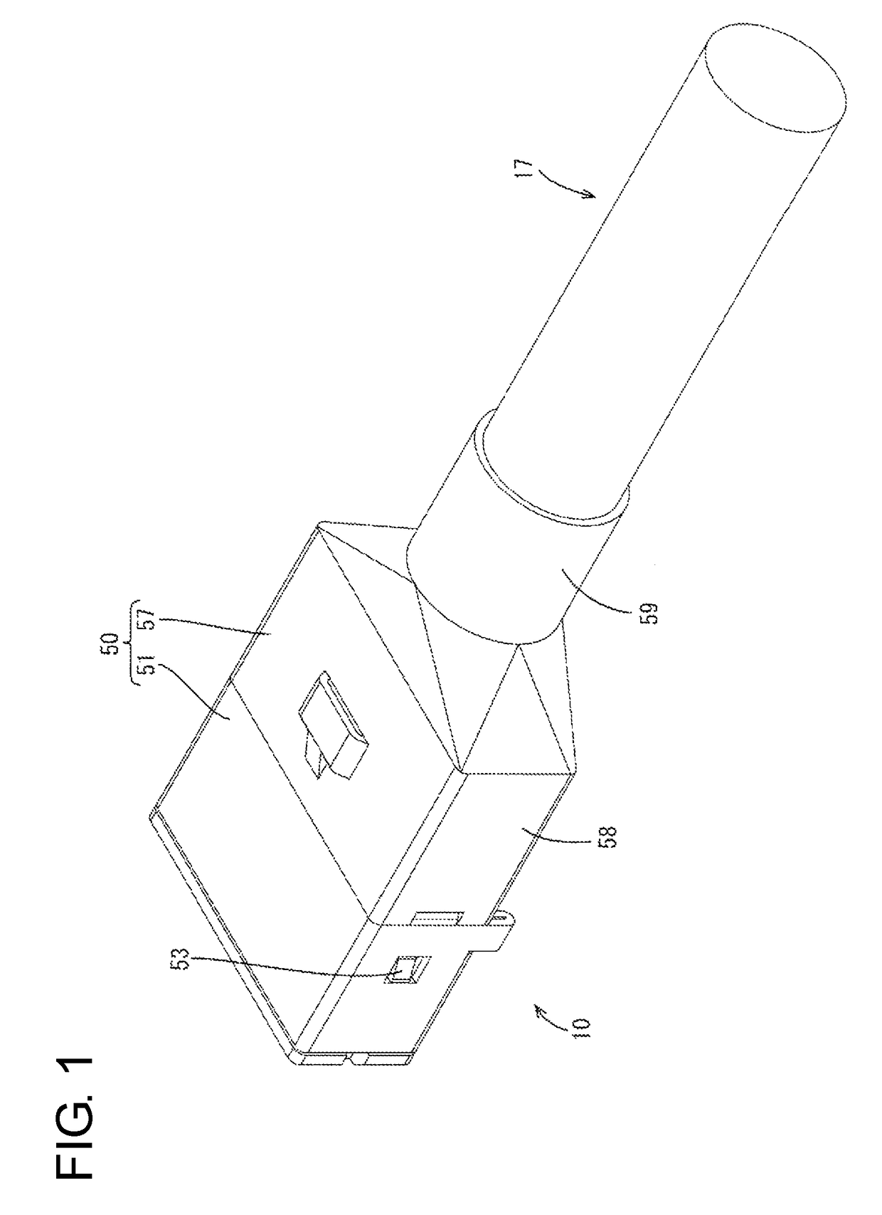
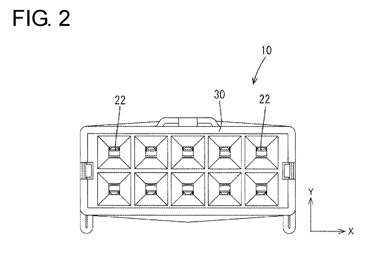
[0061]A first embodiment is described with reference to FIGS. 1 to 13. A communication connector 10 is installed in a vehicle, such as an electric vehicle or hybrid vehicle, and is arranged in a wired communication path between an in-vehicle electric component (navigation system, ETC system, monitor, etc.) in the vehicle and an external device (camera, etc.) or between in-vehicle electric components. In the following description, a vertical direction (Y-axis) and a lateral direction (X-axis) are based on directions of FIG. 2, and a left side and a right side of FIG. 4 are referred to as a front side and a rear side concerning a front-rear direction (Z-axis).
[0062]The communication connector 10 of this embodiment includes, as shown in FIG. 3, a shielded cable 17 having a plurality of (ten in this embodiment) wires 11, 12, 13 and 14. The wires 11 are composed of two sets of first wires 11A to 11C, and the wires 12 are composed of one set of second wires 12A, 12B. Terminals 20 are conn...
case 50
(Shield Case 50)
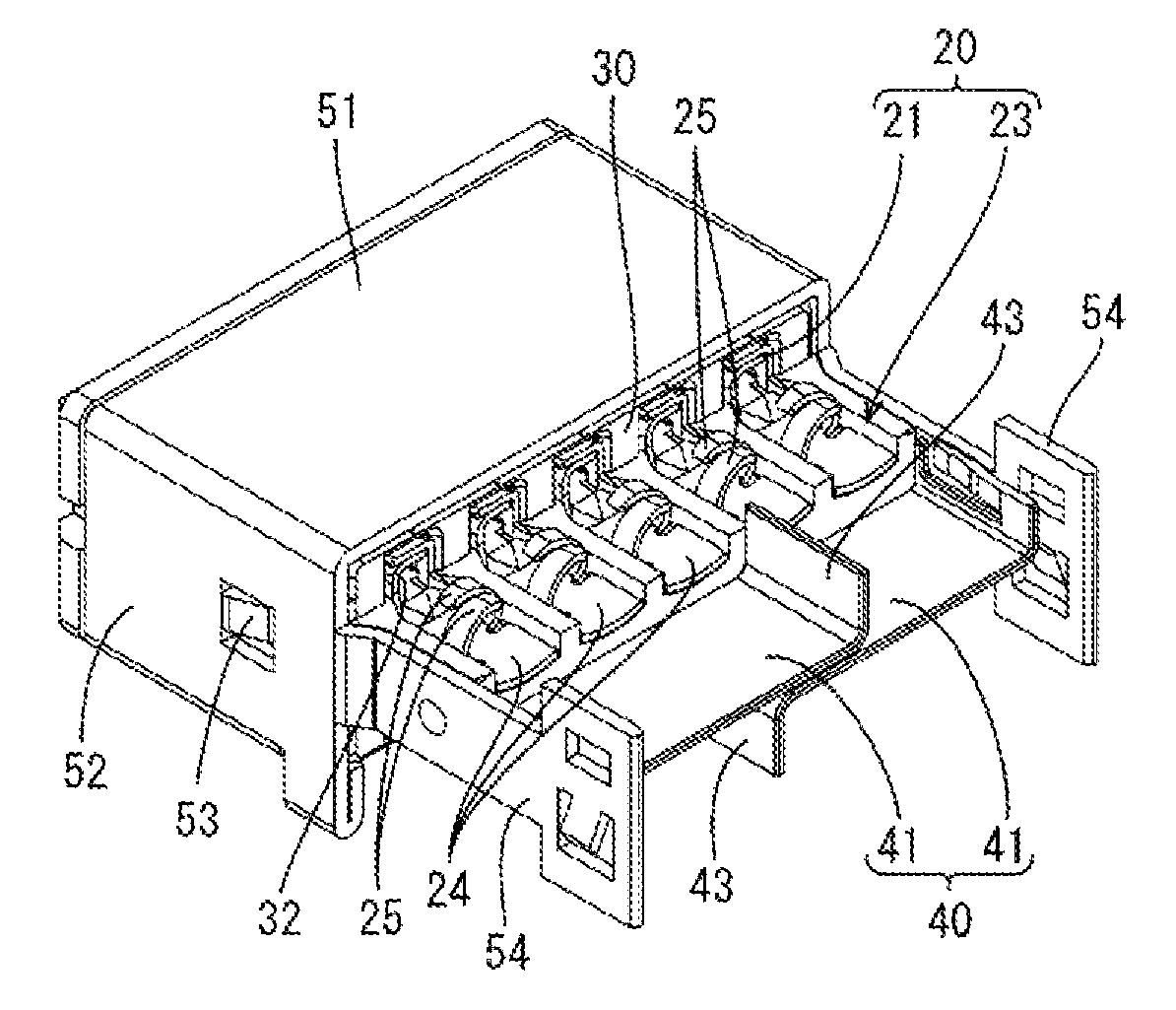
[0074]As shown in FIG. 1, the shield case 50 includes a first shield case 51 for covering the body 31 of the housing 30 and a second shield case 57 arranged behind the first shield case 51 for covering the wires 11 to 14. The first shield case 51 is made of metal, such as aluminum or aluminum alloy, and includes, as shown in FIG. 3, a housing surrounding portion 52 in the form of a rectangular tube for surrounding the housing 30 and coupling portions 54 to be connected to the shield case 57. Locked portions 53 formed of resiliently deformable resilient pieces are provided on left and right side surfaces of the housing surrounding portion 52. When the first shield case 51 is fit into the housing 30 from behind the housing 30, the locked portions 53 are locked to locking portions 33 (see FIG. 7) formed by cutting side surfaces of the housing 30. Each coupling portion 54 is a plate extending rearward from the rear end of the side surface of the housing surrounding porti...
third embodiment
[0095]the invention is described with reference to FIGS. 26 to 31.
[0096]In the third embodiment, wire connecting portions 82 of terminals 81 are crimped and connected to wires 11 to 14, as shown in FIG. 26. The same components as in the above embodiments are denoted by the same reference signs and not described.
[0097]The wire connecting portion 82 of the terminal 81 includes two wire barrel portions 83 and two insulation barrel portions 84 standing from both side edges of a bottom plate. The wire barrel portions 83 are crimped to a conductor exposed at an end part of the wire 11 to 14, and the insulation barrel portions 84 are crimped to hold an insulation coating of the wire 11 to 14.
[0098]An extending portion 88 extends rearward while having a smaller thickness than a housing 86. The extending portion 88 is formed with a plurality of placing portions 87 arranged on the upper and lower surfaces of the extending portion 88 such that the wire connecting portions 82 are placed thereon...
PUM
 Abstract
Description
Claims
Application Information