
Controlling a display based on different modes of operation

a display and control technology, applied in the field of electronic equipment, can solve the problems of insufficient battery charging, inability to obtain the current necessary for the transmission operation of image data, and poor charging efficiency, and achieve the effect of maintaining the charging efficiency of the battery and efficient charging of the battery

Active Publication Date: 2018-11-06
SONY CORP
View PDF26 Cites 1 Cited by
  • Summary
  • Abstract
  • Description
  • Claims
  • Application Information

AI Technical Summary

Benefits of technology

The technology described in this patent allows for efficient battery charging while continuing to use the device. It does this by controlling the maximum current allowed and using external feeding power while maintaining charging efficiency, even as the battery level decreases. Additionally, it also allows for executing operations that require more power than what the battery can provide, using the battery to discharge and provide the necessary power. Overall, this technology improves the performance and functionality of electronic devices.

Problems solved by technology

In this case, because only an amount obtained by subtracting a current value necessary for the apparatus operation is allocated to the charging, charging efficiency is not good (for example, refer to Patent Document 2).
That is, the operation charging has a problem in that sufficient charging of the battery cannot be executed for consumption of the power by the apparatus operation.
However, when the maximum current standard is low as in the USB feeding, a current necessary for the transmission operation of the image data may not be obtained.
In addition, in the digital camera, an operation such as driving of a lens barrel also needs large power more than a predetermined rating of the USB cable.
As such, depending on the remaining capacity of the battery, the apparatus operation that is enabled during the charging is restricted.
Therefore, usability is not good.
However, in the wireless communication apparatus, if charging efficiency of the battery at the time of the operation charging is not improved, a problem of the restriction of the apparatus operation cannot be resolved in a state in which the operation charging is enabled.

Method used


Image

  • Controlling a display based on different modes of operation
  • Controlling a display based on different modes of operation
  • Controlling a display based on different modes of operation

Examples


Embodiment Construction

[0057]Hereinafter, embodiments of the technology disclosed in the present specification will be described in detail with reference to the drawings.

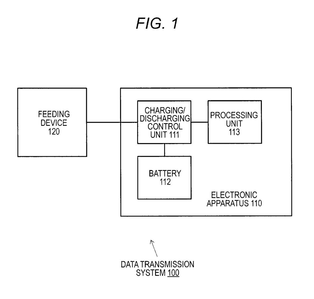
[0058]FIG. 1 schematically illustrates a configuration of a data transmission system 100 to which the technology disclosed in the present specification is applied. The data transmission system 100 illustrated in the drawing includes an electronic apparatus 110 and a feeding device 120 to externally supply power to the electronic apparatus 110.

[0059]The feeding device 120 may obtain feeding power using a commercial power supply as a power supply, and may obtain feeding power from a USB host (not illustrated in the drawings) such as a personal computer. Also, it is assumed that the feeding device functions as a cradle to be USB-connected and obtains the feeding power from the USB host. When the feeding device 120 obtains the feeding power from the USB host, a maximum current that can be supplied to the electronic apparatus 110 depends on th...


PUM

PropertyMeasurementUnit
currentaaaaaaaaaa
currentaaaaaaaaaa
threshold valueaaaaaaaaaa

Abstract

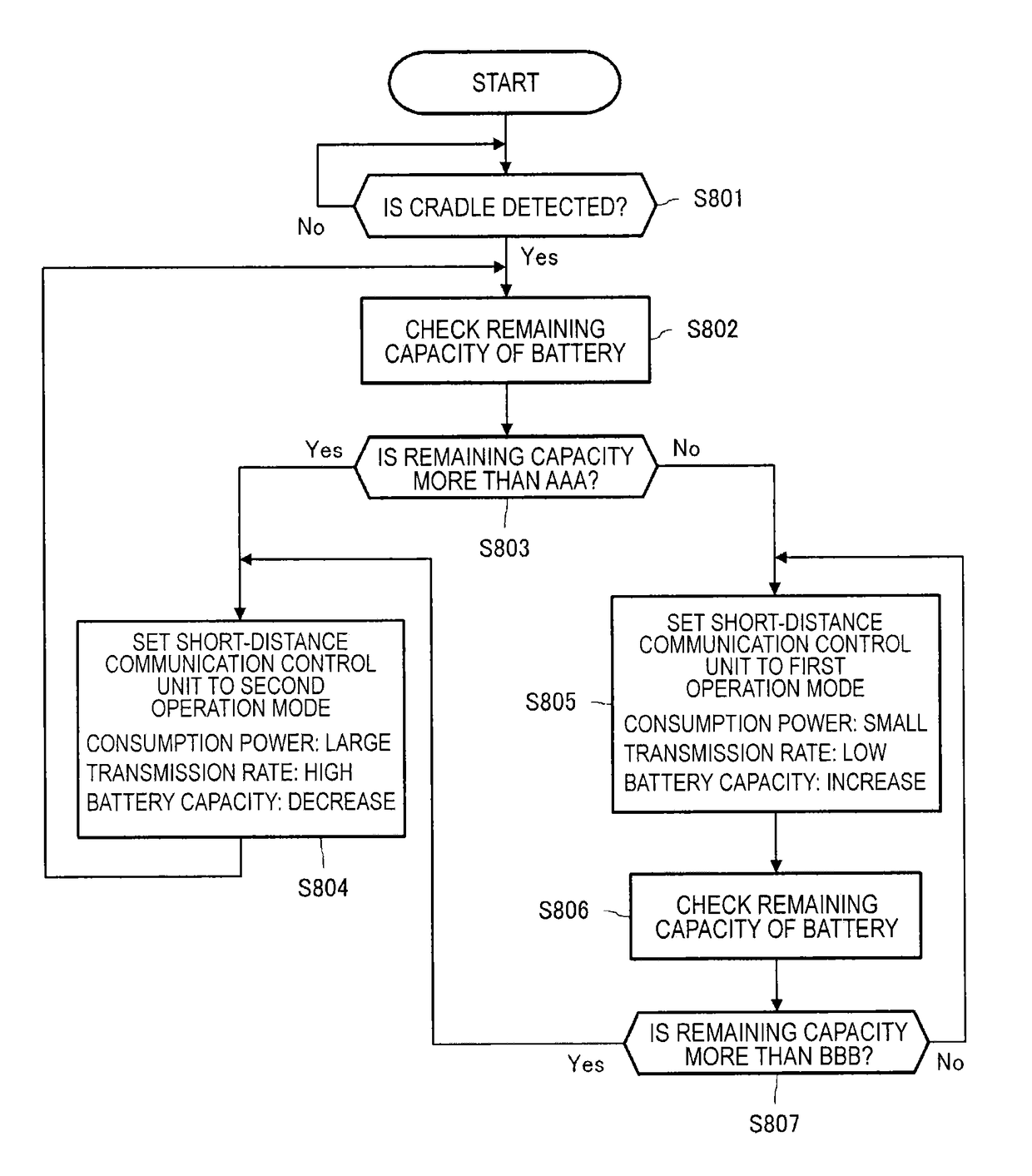
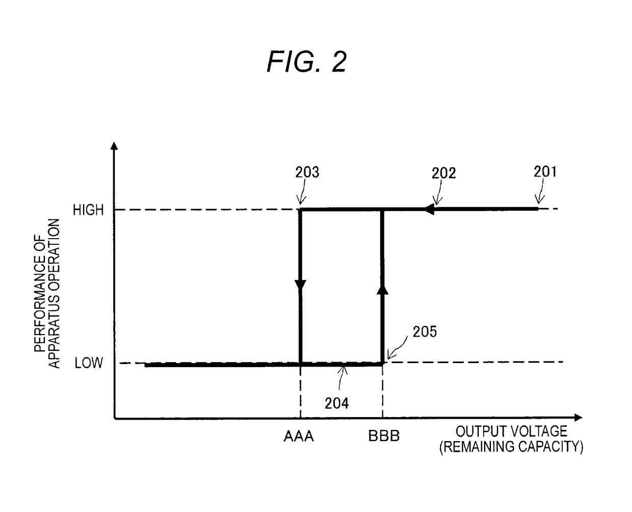
An electronic apparatus is provided with a processing unit that has a first operation mode in which an operation is enabled using only external power from a feeding device and a second operation mode in which the operation is enabled by feeding from a battery in addition to the external power from the feeding device. When the remaining capacity of the battery is sufficient, the processing unit executes an apparatus operation in the second operation mode. However, when the remaining capacity of the battery decreases, the processing unit changes an operation mode to the first operation mode and executes charging of the battery while continuously executing the apparatus operation.

Description

TECHNICAL FIELD[0001]The technology disclosed in the present specification relates to an electronic apparatus capable of operating by a battery, a charging control method, and a data transmission system and particularly, to an electronic apparatus capable of executing an apparatus operation and charging of a battery at the same time, a charging control method, and a data transmission system.BACKGROUND ART[0002]Recently, portable apparatuses such as a digital camera, a mobile phone, a tablet terminal, and a notebook computer spread broadly. Most of these kinds of apparatuses are driven by a battery.[0003]When a second battery is used as the battery, the battery can be used repetitively by charging. When the battery is charged, power supplied from a commercial power supply or a charger is used. In a large number of apparatuses driven by the battery, “operation charging” in which the battery is charged while an apparatus body is operated in a state in which the apparatus is connected t...

Claims


Application Information

Patent Timeline
Patent Type & Authority Patents(United States)
IPC IPC(8): G06F1/28H02J7/02H04B5/00H01M10/44H02J50/80H02J50/10H02J7/00H01M10/42H02J7/34H04B5/48
CPCH02J7/007H01M10/44H02J7/0068H02J7/025H02J50/10H02J50/80H04B5/0031H04B5/0037G06F1/28Y02B40/90H01M2010/4278H02J7/0052H02J2007/005H02J2007/0062H02J2007/0096H04B5/0081H02J7/00034H02J7/0048Y02E60/10H04B5/26H04B5/79H04B5/24H02J7/00Y02B40/00H04B5/72
Inventor OISHI, TAKASHI
Owner SONY CORP
Learn More