LC filter

a filter and filter body technology, applied in the field of lc filters, can solve the problems of reducing the q value, unable to achieve the reduction of the size of an element and the increase of the inductance value, and achieve the effect of q value and large inductance valu

Active Publication Date: 2018-11-06
MURATA MFG CO LTD
View PDF23 Cites 0 Cited by
  • Summary
  • Abstract
  • Description
  • Claims
  • Application Information

AI Technical Summary

Benefits of technology

[0007]Preferred embodiments of the present invention provide LC filters with which a large inductance value is able to be obtained and a Q value is able to be improved.
[0009]According to preferred embodiments of the present invention, a large inductance value is able be obtained and a Q value is able to be improved.

Problems solved by technology

In the low-pass filter disclosed in Japanese Unexamined Patent Application Publication No. 2013-21449, a decrease in Q value is a problem.
In a case where a loop-type inductor is used, it is therefore difficult to achieve both the size reduction of an element and the increase in inductance value.

Method used


Image

  • LC filter
  • LC filter
  • LC filter

Examples


Embodiment Construction

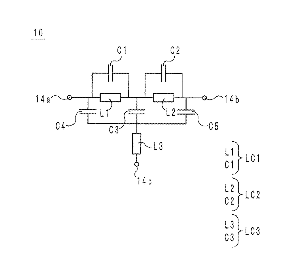
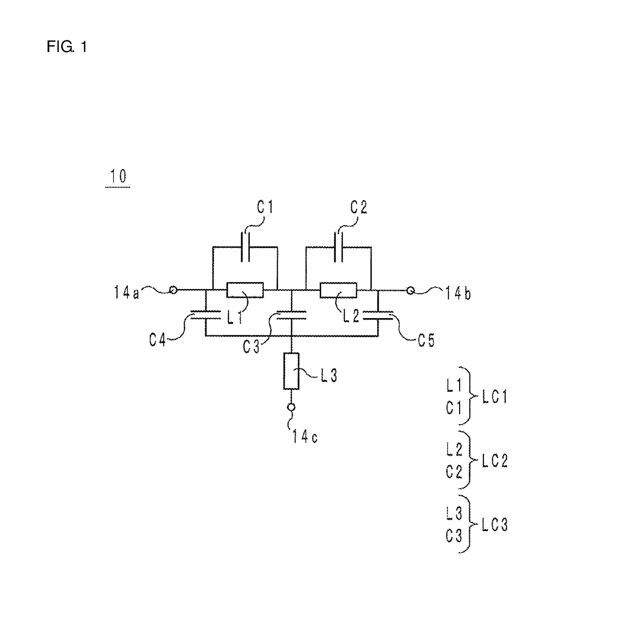
[0021]A circuit configuration of an LC filter 10 according to a preferred embodiment of the present invention will be described with reference to the accompanying drawings. FIG. 1 is an equivalent circuit diagram of the LC filter 10.

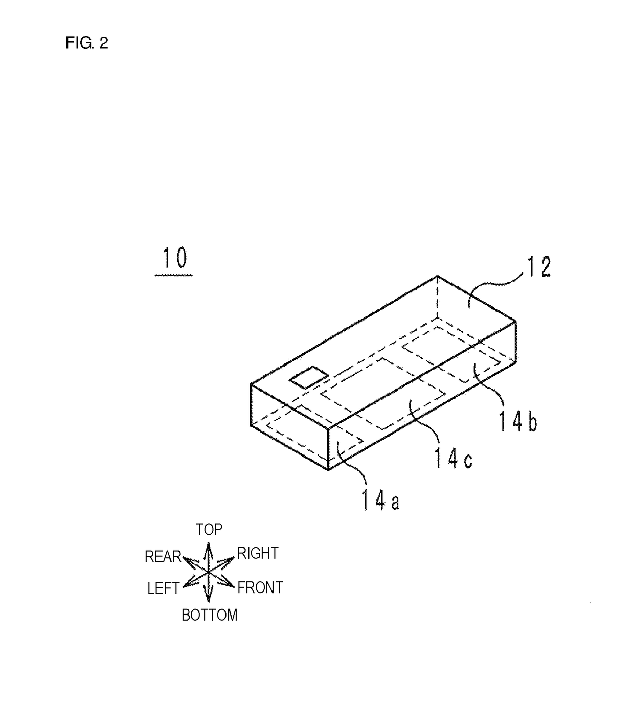
[0022]As illustrated in FIG. 1, the LC filter 10 includes inductors L1 to L3, capacitors C1 to C5, and outer electrodes 14a to 14c. The outer electrodes 14a and 14b are high-frequency signal input / output terminals. The outer electrode 14c is a ground terminal connected to a ground potential.

[0023]The inductor L1 and the capacitor C1 are electrically connected in parallel to define an LC parallel resonator LC1. The inductor L2 and the capacitor C2 are electrically connected in parallel to define an LC parallel resonator LC2. The LC parallel resonators LC1 and LC2 are connected in series in this order between the outer electrodes 14a and 14b. The inductors L1 and L2 are electromagnetically coupled to each other.

[0024]One electrode of the capacitor C3 is co...


PUM

PropertyMeasurementUnit
cutoff frequencyaaaaaaaaaa
resonant frequencyaaaaaaaaaa

Abstract

An LC filter includes a laminate including insulating layers laminated in a lamination direction, an inductor having a spiral or helical shape around an axis parallel or substantially parallel to the lamination direction, and a capacitor in which capacitor conductors face each other. The inductor and the capacitor do not overlap as viewed from the lamination direction and all directions orthogonal or substantially orthogonal to the lamination direction.

Description

CROSS REFERENCE TO RELATED APPLICATIONS[0001]This application claims the benefit of priority to Japanese Patent Application No. 2015-144497 filed on Jul. 22, 2015 and is a Continuation Application of PCT Application No. PCT / JP2016 / 070153 filed on Jul. 7, 2016. The entire contents of each application are hereby incorporated herein by reference.BACKGROUND OF THE INVENTION1. Field of the Invention[0002]The present invention relates to an LC filter including an inductor and a capacitor.2. Description of the Related Art[0003]As an invention concerning an LC filter in the related art, a low-pass filter disclosed in Japanese Unexamined Patent Application Publication No. 2013-21449, for example, is known. The low-pass filter includes a laminate, a coil, and a capacitor. In the laminate, a plurality of insulating layers are laminated in a lamination direction. The coil is incorporated in the laminate, and has a helical shape turning around an axis parallel to a lamination direction. The capa...

Claims


Application Information

Patent Timeline
Patent Type & Authority Patents(United States)
IPC IPC(8): H03H7/075H01F17/00H03H7/01H01P1/203H01F27/00H03H1/00
CPCH03H7/075H01F17/00H01P1/20345H03H7/0115H01F27/00H03H2001/0085H01F17/0013H01F2017/0026
Inventor MASUDA, HIROSHI
Owner MURATA MFG CO LTD
Why Eureka
Try Eureka