Energy-storage pulse device

A pulse and energy storage technology, applied in circuit devices, battery circuit devices, transportation and packaging, etc., can solve problems such as low voltage and difficult booster circuits

Inactive Publication Date: 2019-01-11
叶宝华
View PDF4 Cites 0 Cited by
  • Summary
  • Abstract
  • Description
  • Claims
  • Application Information

AI Technical Summary

Problems solved by technology

In some cases, the charging signal is a pulse signal, such as charging through radio frequency reading and writing signals, usually the voltage when the radio frequency signa

Method used


Image

  • Energy-storage pulse device

Examples


Embodiment Construction

[0014] In order to more clearly illustrate the technical solution of the present invention, the claims of the present invention will be further described in detail below in conjunction with specific embodiments and drawings. It can be understood that the following drawings only show some embodiments of the present invention, so It should not be regarded as a limitation on the scope, and any limited number of modifications made by anyone within the scope of the claims of the present invention are still within the scope of the claims of the present invention.

[0015] It should be understood that, in the description of the present invention, it should be explained that the orientation or positional relationship indicated by the terms "upper", "lower" and so on is based on the orientation or positional relationship shown in the drawings, or the orientation or positional relationship indicated by the product of the invention. Orientation or positional relationship that is conventio...


PUM


Abstract

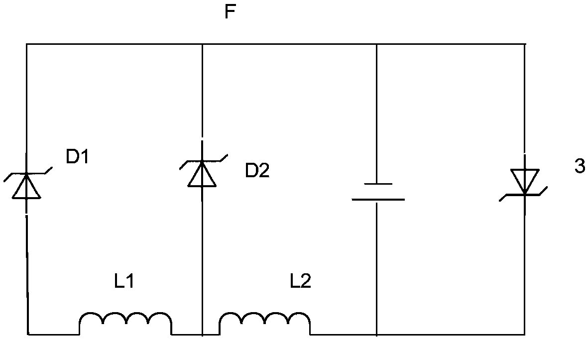
An energy storage pulse device includes a first inductor and a second inductor, the two terminals of the first inductance are respectively connected with one end of the first voltage stabilizing tubeand the second voltage stabilizing tube, a first common contact is arranged between the first inductance and the positive electrode of the second voltage stabilizer tube, two negative electrodes of the first voltage stabilizer tube and the second voltage stabilizer tube are connected to form a second common contact, and a second inductance, a battery and a third voltage stabilizer tube after beingconnected in parallel are arranged in series between the first common contact and the second common contact, and the second inductance value is larger than the first inductance. When the energy storage pulse device receives the RF read-write signal, a large inductive current is generated on the first inductor in the direction of the second inductor, and the third voltage regulator is turned off,and the second inductor increases the voltage to charge the battery; and when the RF read-write signal is received, the first inductor generates a large inductive current in the direction of the second inductor. When the voltage across the second inductor is greater than the reverse breakdown voltage of the third transistor, both the first inductor and the second inductor are in a short circuit state, the third transistor is turned off in the reverse direction, and the first inductor and the second inductor are turned on forward. As that first inductor acquire electrical energy, the battery iscontinuously charged with the acquire energy during the RF reading process. The structure can be charged by radio frequency signal, and the structure is simple and compact.

Description

technical field [0001] The invention relates to the technical field of energy storage, in particular to an energy storage pulse device. Background technique [0002] Existing energy storage typically takes a few minutes to charge a tiny battery. In some cases, the charging signal is a pulse signal, such as charging through radio frequency reading and writing signals, usually the voltage when the radio frequency signal is obtained is small, if the radio frequency signal is used for charging, it is necessary to arrange a more complex boost circuit in a limited space There are difficulties. . Contents of the invention [0003] The technical problem mainly solved by the present invention is to provide an energy storage pulse device, which can be charged by radio frequency signals, and has a simple and compact structure. [0004] In order to solve the above problems, the present invention provides an energy storage pulse device, which includes a first inductance and a second...

Claims


Application Information

Patent Timeline
IPC IPC(8): H02J50/20H02J7/34
CPCH02J7/34H02J50/20
Inventor 叶宝华
Owner 叶宝华
Why Eureka
Try Eureka