Multilayer triplexer

a triplexer and multi-layer technology, applied in the field of multi-layer triplexers, can solve problems such as band mixing

Active Publication Date: 2022-09-27
MURATA MFG CO LTD
View PDF21 Cites 0 Cited by
  • Summary
  • Abstract
  • Description
  • Claims
  • Application Information

AI Technical Summary

Benefits of technology

[0011]Preferred embodiments of the present invention provide multilayer triplexers that each eliminate or reduce the possibility that signals in a band will pass through a stray capacitance and will consequently be mixed with signals in another band.
[0015]When the first and second coil conductor patterns do not coincide with each other in the width direction, the stray capacitance is able to be reduced or prevented. This layout eliminates or reduces the possibility that signals in a band will pass through the stray capacitance and will consequently be mixed with signals in another band.
[0017]As described above, the area of the region enclosed by the coil conductor pattern of the coil concerned is larger than the area of the region enclosed by the coil conductor pattern of any other coil. Of a plurality of coil conductor patterns included in the same coil, a coil conductor pattern between two layers and a coil conductor pattern between another two layers entirely overlap each other in the width direction. As a result of these features, a larger inductance value is able to be obtained.
[0019]Multilayer triplexers according to preferred embodiments the present invention each include the first coil connected as a stage preceding the first filter, the second coil connected as a stage preceding the second filter, and a third coil connected as a stage preceding the third filter. Unlike the triplexer known in the art, the multilayer triplexers according to preferred embodiments of the present invention do not include parallel resonant circuits each of which include a coil and a capacitor and connected as a stage preceding a corresponding filter. These multilayer triplexers thus eliminate the possibility that signals in a band will pass through a capacitor of a parallel resonant circuit and will consequently be mixed with signals in another band.
[0020]In multilayer triplexers according to preferred embodiments of the present invention, the coil conductor pattern of the first coil, the coil conductor pattern of the second coil, and the coil conductor pattern of the third coil do not overlap each other when the multilayer body is seen through in the direction in which the substrate layers are stacked on one another. As a result of this feature, stray capacitance between the coil conductor patterns of different ones of these coils is able to be reduced or prevented. The multilayer triplexer thus eliminates or reduces the possibility that signals in a band will pass through the stray capacitance and will consequently be mixed with signals in another band.

Problems solved by technology

A disadvantage of the triplexer 1000 is that signals in a band may be mixed with signals in another band through the capacitor of the first parallel resonant circuit X1, the capacitor of the second parallel resonant circuit X2, or the capacitor of the third parallel resonant circuit X3.

Method used


Image

  • Multilayer triplexer
  • Multilayer triplexer
  • Multilayer triplexer

Examples


Embodiment Construction

[0031]Hereinafter, preferred embodiments of the present invention will be described with reference to the drawings.

[0032]The following preferred embodiments of the present invention are merely illustrative and should not be construed as limiting the scope of the present invention. The drawings are provided to facilitate the understanding of the preferred embodiments and may include schematic illustrations. For example, the dimension ratios of components illustrated in the drawings or the relative dimension ratios of the components may be inconsistent with the corresponding dimension ratios described in the description. Some of the components described in the description may be omitted from a drawing, or one or some of the same components may be omitted from a drawing.

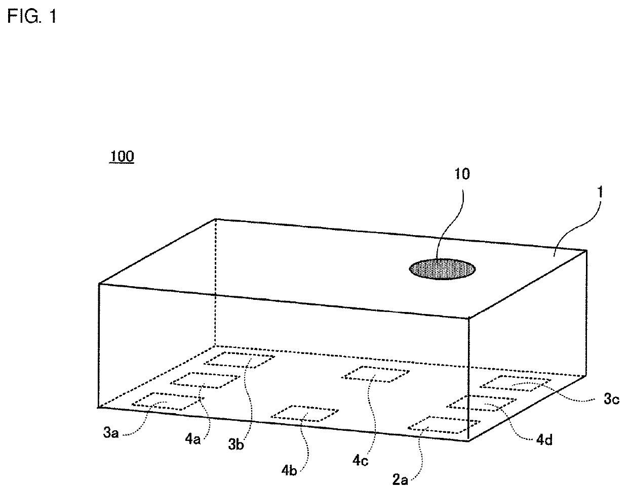
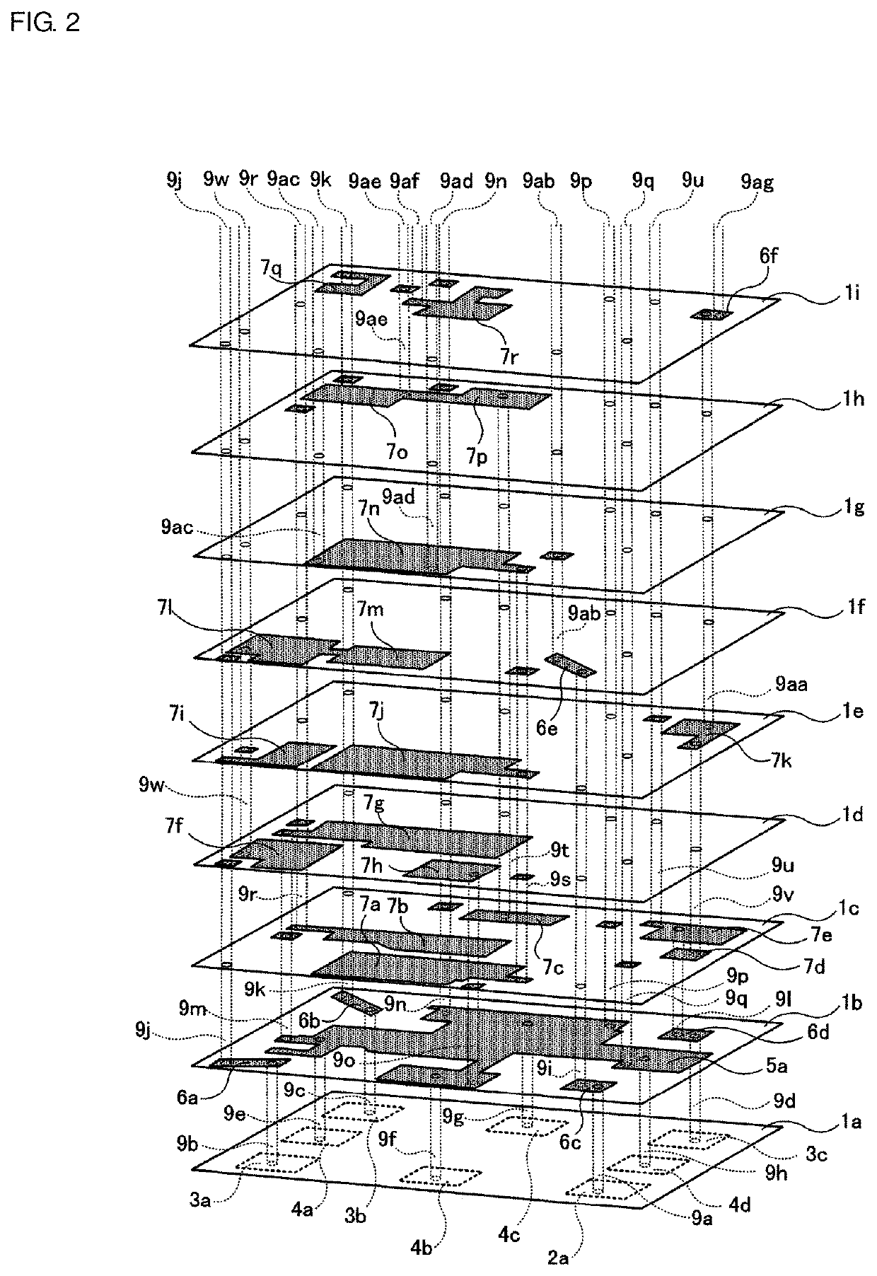
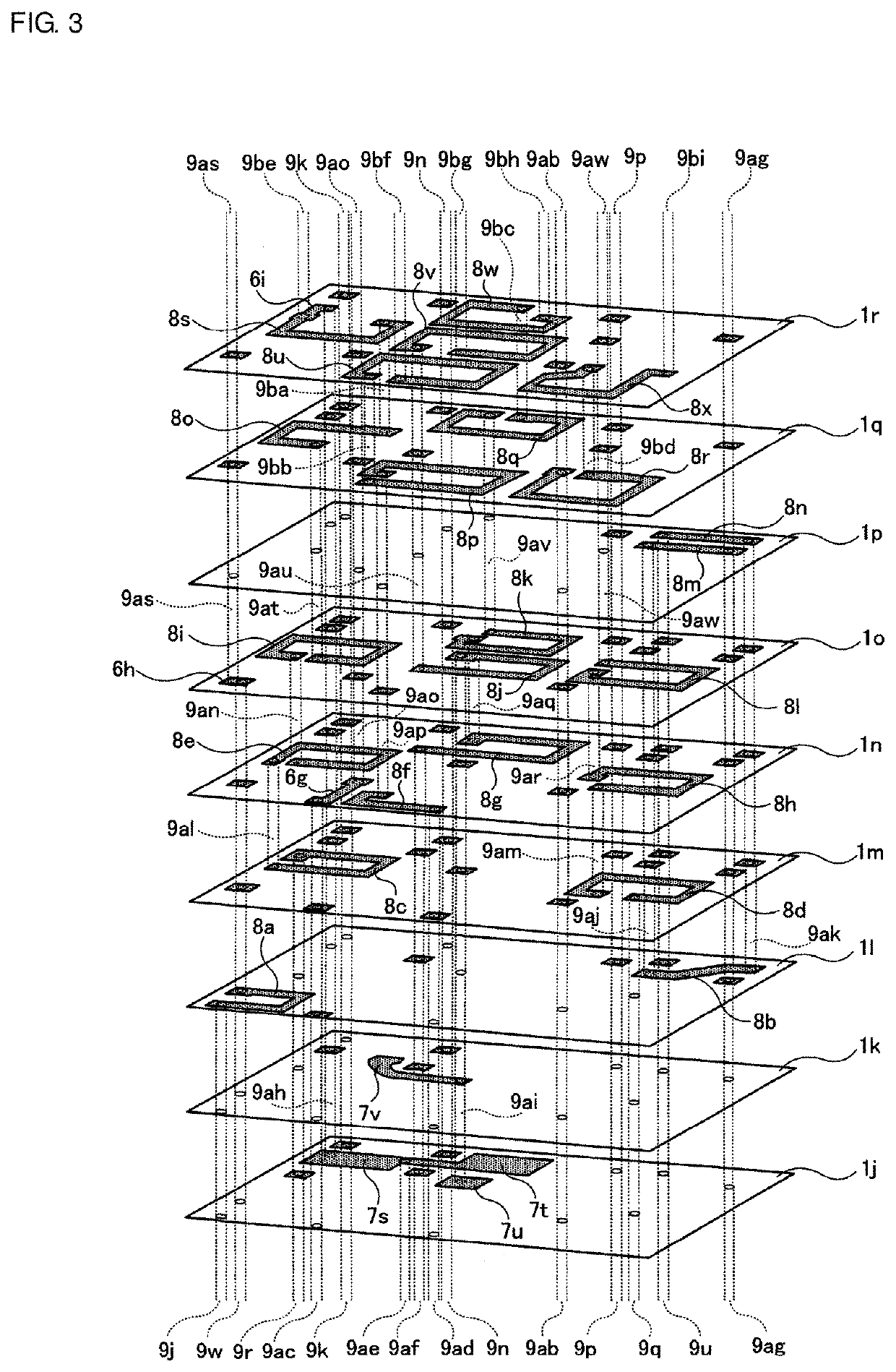
[0033]FIGS. 1 to 4 illustrate a multilayer triplexer 100 according to a preferred embodiment of the present invention. FIG. 1 is a perspective view of the multilayer triplexer 100. FIGS. 2 to 4 are exploded perspective ...


PUM

PropertyMeasurementUnit
frequencyaaaaaaaaaa
frequencyaaaaaaaaaa
frequencyaaaaaaaaaa

Abstract

A multilayer triplexer includes a first coil connected between a common terminal and a first filter, a second coil connected between the common terminal and a second filter, and a third coil connected between the common terminal and the third filter. The first coil, the second coil, and the third coil each include a coil conductor pattern between ones of substrate layers of a multilayer body. The coil conductor pattern of the first coil, the coil conductor pattern of the second coil, and the coil conductor pattern of the third coil do not overlap each other when the multilayer body is seen through in a direction in which the substrate layers are stacked on one another.

Description

CROSS REFERENCE TO RELATED APPLICATIONS[0001]This application claims the benefit of priority to Japanese Patent Application No. 2018-043657 filed on Mar. 9, 2018 and is a Continuation Application of PCT Application No. PCT / JP2019 / 006720 filed on Feb. 22, 2019. The entire contents of each application are hereby incorporated herein by reference.BACKGROUND OF THE INVENTION1. Field of the Invention[0002]The present invention relates to a multilayer triplexer including a multilayer substrate in which substrate layers are stacked on one another.2. Description of the Related Art[0003]Triplexers are widely used in electronic devices such as mobile communication devices, most notably mobile phones and smartphones. For example, International Publication No. 2008 / 075691 discloses a triplexer. FIG. 9 illustrates a triplexer 1000, which is the triplexer disclosed in International Publication No. 2008 / 075691.[0004]The triplexer 1000 includes a common terminal Pc, a first branch terminal P1, a sec...

Claims


Application Information

Patent Timeline
Patent Type & Authority Patents(United States)
IPC IPC(8): H03H7/46H03H1/00H03H7/01H03H7/38
CPCH03H7/463H03H1/00H03H7/1766H03H7/38H03H2001/0085H01F27/00H01F17/00H03H7/1758
Inventor NAKASHIMA, YASUHIRO
Owner MURATA MFG CO LTD
Why Eureka
Try Eureka